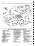
| Book |
Page |
Context |
 |
 |
Replacement 8 46 Adjustment 8 46 T 3 Aimers 8 48 Aiming Screen Method 8 52 Lighting Switch Replacement 8 52 Stoplight Switch Replacement 8 52 Dimmer Switch Replacement 8 52 Windshield Wiper Switch Replacement ...
52 Neutral Safety Switch Replacement 8 52 Back Up Lamp Switch Replacement 3 Speed only 8 55 Instrument Panel Compartment Lamp Switch Replacement 8 55 Bulb and Lamp Body Service 8 55 Parking Lamp |
|
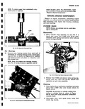 |
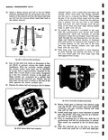
press is required J 7048 J 3ss 1 Fig 6A 50 Remevinp Crankshaft Gear Ma i Bearings 52 Remove main bearing inserts from each half of rankshaft by rotating bearing insert with fingers ...
with off set jaws compress valve spring and remove valve locks as shown in Figure 6A 52 1 L r 1 a 1 Fig 6A 52 Removing Valves Using Tool J 8064 2 Release Tool |
|
 |
Cylinder Head 6A 51 Push Rod Oil Drain Tube 6A 51 Engine Rear Housing 6A 52 Crankshaft Pulley 6A 52 Oil Cooler 6A 52 Exhaust Manifolds 6A 53 Valve Lash Adjustment 6A 53 Oil Filter |
|
 |
increased or decreased by bending up washer tab and tightening or loosening the adjusting nut fig 10 52 Tightening the adjusting nut will increase effort required to open and close ventilator loosening adjusting nut will ...
obtained bend down washer tab to lock nut in position b ADJUSTING WASHER TAB NUT Fig 10 52 V ntllator Friction Adjustment NOTE This adjustment should be performed as a bench operation WINDOW ASSEMBLY FRONT |
|
 |
suspension is basically the same as the li 10 series passenger car as shown in Figure 3 52 A l components are assembled as a unit with a removal le front suspension crossmember Control arms ...
Series components except as outlined in the following pages 48 Fig 3 52 Front Suspension 1200 Series kND ADJUSTMENTS ADJUSTMENT OF FRONT WHEEL BEARINGS Adjust front wheel bearings as outlined |
|
 |
Exchqnger Opening 41 Filler Rear End Cover Depression Rig 2 12 23 27 lfl7 1 25 26 52 ...
Compartment Cover 50 Plate Rear Bumper Mounting ngi 51 Filler Rear End Outer Panel Left Upper 52 Panel Rear End Outer artment Front 53 Rail Front Compartment Cross ront Compartment Pan 54 Rail Assembly Front |
|
 |
above 050 thrust washer is required c Remove J 8371 and install thrust washer fig 6E 52 selected on front pump hub SELECTIVE CLUTCH DRUM THRUST WASHER Fig 6E 52 Installing front Pump Gasket nnovme |
|
 |
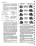
that a tip builds up on one point while a pit forms in the other figs 8 52 and 8 53 The direction in which the tungsten transfers can be used as a basis ...
pitting For instance if the material transfers from the negative to the positive point fig 8 52 one or more of these corrections may be made increase condenser capacity shorten condenser lead separate distributor |
|
 |
form a friction brake turn the ring gear back and forth with a wrench fig 6C 52 on the ring gear mount ing bolts until a definite contact pattern is formed on the pinion |
|
 |
Wire Diameter 66 Outside Diameter 4 78 Pitch Diameter 4 11 Overall Free Height 12 52 Height at Normal Load 7 42 1922 lb Deflection Rate at Spring 580 lb iir Deflection Rate at Wheel |
|
 |
52 |
|
 |
52 Material Transfer Nogative to Positive Point r f i a r 711 Fig S3 Material Transfer Positive to N Sativ Point not be used on other metals and should not be allowed to become |
|
 |
Brace Rear Cross Bar To Rear Rail Upper linge Upper 51 Extension Rear End Outer Panel 52 Bar Rear Cross artmenf Front 53 Roil Front Compartment Cross ront Compartment Pan 54 Rail Assembly Front Compartment |
|
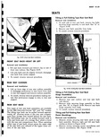 |
SEAT BACK Two types of rear seat back assemblies are available i for the 1961 Chevrolet Corvair 52 and 727 models The tilting type back can be pulled forward approximately 45 allowing access |
|
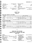 |
Advertised Gross Horsepower Rating 80 4400 rpn Braking Lever Ratios Pedal ratio 6 8 Hydraulic 4 52 i Overall 30 74 i PARKING BRAKE Type Mechanical pull type i cables to rear service brakes Total |
|
 |
Servo Piston Return Spring 36 Stator Shaft 51 Clutch Drum Piston 37 Pinion Shaft Rear Oil Seal 52 Clutch Drum Hub 38 Pinion Shaft Bushing 53 Clutch Drum Selective Thrust 39 Rear Pump Wear Plate |
|
 |
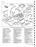
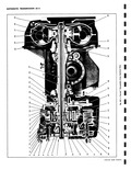
52 56 49 46 57 47 58 o o P 59 Pow rglide Exploded View CORVAIR SHOP MANUAL |
|
 |
Governor Drive Gear 51 Low Servo Piston Cushion 35 Turbine Shaft Front Bushing Spring 36 Turbine Shaft 52 Low Servo Piston Cushion 37 Turbine Shaft Rear Bushing Spring Seat 38 Converter Assembly 53 Low Servo |
|
 |
52 |
|
 |
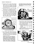
SHAFT SHAFT channel slightly with a small drift and insert the reverse shifter head shaft fig 6D 52 partially into the case to compress the detent Then engage the pin of the reverse shifter head |
|
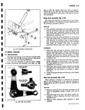 |
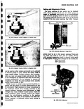
52 Installation of Steering Gear Sl iERING LINKAGE Ti Rod Assembly escription and service of tie rods are covered under C o 500 700 and 900 Steering Service Operations ie Rod except for following difference |
|
 |
PRESSURES lPSll Condition R N D L Disconnect TV rod at carburetor and vacuum hose 0 0 52 54 66 77 at balance tube Depress accelerator to W O T By disconnecting |