| Book |
Page |
Context |
 |
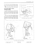 |
pound curve for all styles see 1E 25 for I V 16000 25000 26000 35000 36000 45000 Lind 46000 I If II I I I jIC Series ...
IRUBBERI W relationship to each other see Fig 1E 2 7 for I 16000 25000 26000 35000 36000 45000 and 46000 Series and Fig 1E 28 for 38000 48000 and 68000 Fig IF26 Reor Ouurter |
 |
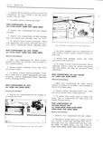 |
VACUUM RELEASE UNIT ga a og V ALL 25000 26000 35000 36000 38000 OC g R KER L 45000 46000 AND 48000 SERIES CEE N5 awv l Removal r1d IDSTDHCHIOVI MODELING CLAY 4 l Remove ...
Series and Fig lFl6 for Fig lFI3 Re Compartment Lid Lock ond Sniker 35000 36000 38000 45000 46000 and 48000 Series |
 |
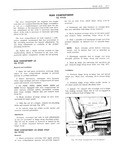 |
Position hinge strap within scribe marks on 3 Oh 35000 36000 38000 45000 46000 and lid inner panel and install attaching bolts 48000 Series equipped with rear compartment lid lock vacuum release option disconnect vacuum |
 |
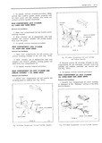 |
procedure li 7 Y A REAR c0Mr ARrMsm Locx cvunpsn RETAINER ll A SHAFT ALL 35000 AND 36000 SERIES r Removal und l s ll a VIEW A mu 1 Open rear compartment |
 |
 |
employed to guard against molding damage The exterior moldings for Body Series 15000 16000 25000 26000 35000 36000 38000 45000 46000 48000 and 68000 are illustrated in Figures 1K3 thru 1K5 1K6 thru lK9 lKl0 |
 |
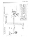 |
Circuit Diagram Switch in Sect Side Pune 35 36000 Series |
 |
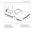 |
36000 Series 57 Styles l Windshield Pillar Drip Melding S Front ot Rear Wheel Opening Molding 2 Roof Drip Melding Front Scalp 9 Rear Wlweel Opening Molding 3 Roof Drip Melding Rear Seelp l0 Rear |
 |
 |
QHCGT NOTE Figure IE 29 is for 16000 25000 26000 35000 36000 45000 and 46000 Series but is REAR QUARTER WINDOW indicative of hardware attachments for all 3 i REGULATOR ASSEMBLY and 5 i Styles |


