| Book |
Page |
Context |
 |
 |
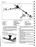
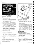
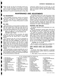
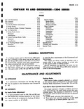
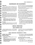
Sector Shaft Bushing Replacement 4 20 Wormshaft Seal 4 20 Side Cover Bushing Replacement 4 21 GENERAL D The steering gear and linkage fig 4 33 are placed forward of the center line ...
compensating for body assembly tolerances ID QREENBR ERiER1ES IEX Page Sector Shaft Seal Replacement 4 21 Wormshaft Seal Replacement 4 21 Wormshaft Bearing Cup Replacement 4 21 Ball Nut Assembly 4 21 Steering Gear Assembly ...
21 Adjustment on Bench 4 22 Installation 4 22 Steering Linkage 4 23 Tie Rods 4 23 Removal 4 23 Installation 4 23 Relay Arm Assembly 4 23 Installation 4 23 Idler |
|
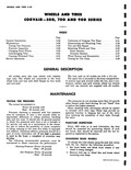 |
Testing Tire Pressures 3 20 Puncture Inspection 3 20 Changing Road Wheels 3 20 Interchanging Tires 3 21 Cleaning Whitewall Tires 3 21 Service Operations 3 21 GENERAL C All models carry disc type wheels ...
Rear 30 pounds ND TIRES O AND 900 SERIES EX Page Correction of Irregular Tire Wear 3 21 Dismounting and Mounting Tires 3 22 Tire and Rim Repair 3 23 Balancing Wheels and Tires |
|
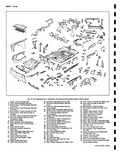 |
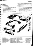
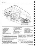
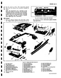
Exploded View Underbody h 1 Support Heat Exchanger Bait 20 Extension Rear 2 Cover Heat Exchanger Opening 21 Extension Heaf 3 Reinforcemenf Heat Exchanger Opening Cover Cover Front 22 Extension Heat 4 Rainforcemenf Heat Exchanger ...
Seat Center At Cordon Shot 19 Cover Rear Seat Pan Duct 37 Plate Engine C 22 23 21 1 24 41 21 1A 13 p 47 45 NY 70 117 4 O OF43 |
|
 |
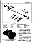
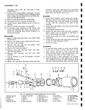
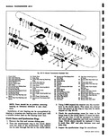
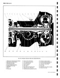
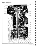
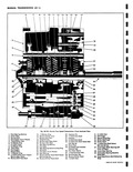
21 I fig bE 1l tervolr Pewerql 1 Valve Body to Transfer Plate 7 low Drive Volvo Inner Spring Attaching Screws 4 Low Drive Valve Outer Spring 2 Transfer Plate 9 Spring Seat 3 Transfer ...
screwdriver between its head and the surface of the main valve body then remove detent valve assembly 21 and throttle valve spring 22 Complete disassembly of the valve body by removing the E ring ...
Regulator Volvo Spring Spring 13 Rear Pump Priming gall 20 Pressure Regulator Valve 16 Hydraulic Modulator Valve 21 Detenl Valve Assembly Body 24 Throttle Valve Spring 17 Hydraulic Modulator Booster 23 Throttle Volvo Valve |
|
 |
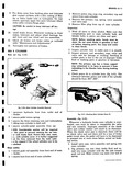
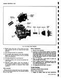
showr in Figure 9 24 4 15 16 12 13 17 18 19 rUU 1 2 0 21 1 1 j wt Cover Exploded 15 Choke Valve rator Pump lb Choke Shaft and Lever ...
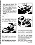
Lever and Swivel 18 Needle Seat Gasket oly 19 Needle seat er Ring 20 Needle Valve Spring 21 Float Assembly 7F r Fig 9 21 Removing Needle Seat 3 Bend tang located just above |
|
 |
21 28 ng Motor Parts Layout 15 Overrunning Clutch Assembly 23 Washer 16 Spring 24 Insulated Brush Holders 17 Collor 23 Grounded Brush Holders 1 Snap Ring 26 Brush 19 Assist Spring 27 Screws ...
Armature 21 Field Coils 20A Broke Washer 29 Insulators 21 Commutator End frame 30 Palo Shoos 22 Brush Springs 31 Screws NOTE A resistance will be felt when removing component from drive housing |
|
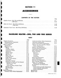 |
Removal 11 18 Disassembly 11 20 Assembly 11 20 Installation 11 20 Spark Plug Replacement 11 21 Nozzle Replacement 11 21 Solenoid Coil Replacement 11 21 Heat Exchanger Replacement 11 22 Heater Unit Complete |
|
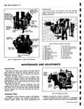 |
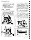
miles of operation or sooner if carburetor flooding occurs Remove the filter element shows in Figure 9 21 and clean by washing in solvent and blowing dry with compressed air When replacing the element ...
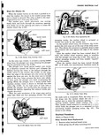
cleaners one at each carburetor 4 3 2 1 25 24 L 23 22 1 I 21 I 20 7 19 10 12 13 13 i 14 15 16 171 118 Fig 9 3 Carburetor ...
Seal Gasket 19 Accelerator Pump 7 Float Drop Adjusting Tang 20 Pump Discharge Volvo 8 Float Needle 21 Pump Discharge Ports 9 Float Hinge Pin 22 Venturi Cluster 10 Float Level Adjusting Tang 23 Choke |
|
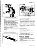 |
fuel solenoid 3 way and five way gant connectors I SPARK PLUG REPLACEMENT Refer to Figures 11 21 11 22 and 11 23 1 Remove burner from heater as indicated WASHERS SLEEVE ELECTRODE ...
ground electrode as described in Item G under Diagnosis Guide NOZZLE REPLACEMENT Refer to Figures 11 21 and 11 24 1 Remove burner louver plate and mixer cup assembly as outlined under Burner Assembly ...
torque 4 Install louver plate and mixer cup assembly SOLENOID COIL REPLACEMENT Refer to Figures 11 21 and 11 25 1 Remove burner assembly as outlined under Burner Assembly 2 Remove screw holding coil cover |
|
 |
Assembly 10 19 Windshield Pillar Drip Moulding 10 19 Windshield Glass 10 19 Windshield Reveal Mouldings 10 21 Instrument Panel Components 10 21 Panel Compartment Door 10 21 Panel Compartment Door Knob 10 22 Panel |
|
 |
21 Exploded View of Heat Excha 1 Solenoid Cup Cover 6 Solenoid Cup Gasket 11 Retc 2 Solenoid Coil 7 Spring 12 Spa 3 Washer 8 Connector 13 Spa 4 Solenoid Cup 9 Filter ...
loud continuous noise when the burner 22 23 24 25 26 18 19 20 21 0 nger Burner and Fuel Solenoid iner Cap 16 Vent Tube 21 Heat Exchanger k Plug Washer 17 Burner Housing |
|
 |
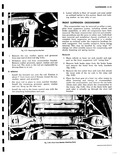
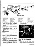
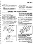
jack with Tool J 7894 under engine as outlined in Section 6 Remove engine rear center shield 21 Remove cotter pin and castellated nut from engine rear mount Lower engine to release weight from engine ...
Engine Side Shield L H 3 Exhaust Duct R H 20 Oil Cooler 10 Oil Filler Tube 21 Engine Rear Center Shield 3 5 Remove bolt upper retainer sleeve mounting and lower retainer ...
21 ft 28 NO 29 Ol 130 r 31 1 Sheet Metal Components 2 Engine Rear Seal 33 Engine Front Shroud L H 3 Engine Rear Seal Retainer 34 Thermostat and Bracket 4 Rear Mount |
|
 |
body as viewed in Figure 6E 11 6 Place throttle valve spring 22 and detent valve assembly 21 in throttle valve bore then depress detent valve assembly 21 and secure to valve body by tapping |
|
 |
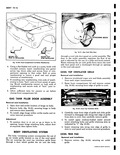
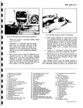
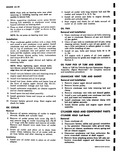
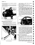
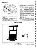
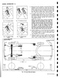
HOIST Figure 1 20 indicates by means of shaded areas n II JACKINC I y Fig 1 21 Corvair 95 those portions of the underbody which hydraulic hoist equipment must bear against when lifting ...
vehicle LIFTING WITH THE AUTO JACK Figure 1 21 indicates the jack locating holes in the frame outriggers of all Corvair 95 models The pin on the load rest of the Corvair 95 auto jack |
|
 |
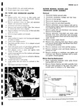
imbedding in the bleeder holes during braking action 4 Check piston fit in cylinder bore fig 5 21 The clearance between piston and wall of the cylinder should be from 001 005 Fig 5 21 |
|
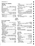 |
Diameter Front 875 rear 9375 Braking Ratio Pedal 6 55 1 Hydraulic 3 29 1 Total overall 21 55 1 Length 840 Location Straddle mounted in steering gear housing Worm and Steering Gear Type Worm ...
other end TURNING RADII Radius Clearance at Curb Weight 19 5 feet Wall to Wall Clearance 21 3 feet KES n 5 Foot Pedal Type Pendant Mounting On brace under dash Line pressure |
|
 |
21 15 16 22 I View of Steering dear ef 16 Boll Guide Retainer 17 Bolts ter Seal 18 Ball Nut aft Bearing Cup 19 Lower Worm Shaft Bearing oft Bearing 20 Lower Worm Shaft ...
Bearing Cup 21 Worm Shaft Bearing Adjuster 22 Worm Shaft Bearing Adjuster nor Screw Lock Nut porarily and proceed with adjustment as outlined in this section under Steering Gear Adjustments Installation 1 With steering gear |
|
 |
21 20 18 19 Fig 10 70a Exploded View 1 Handle 6 Retainer Lock Cylinder 2 Spring 7 Lock Cylinder 3 Escutcheon 8 Handle Retainer 4 Gasket 9 Lock Assembly 5 Panel Reinforcement 10 Upper ...
Screw 14 Locking Knob Inside 19 Lower Rod and Latch Assembly 15 Retainer 20 Remote Control Assembly 21 J Nuts enevWS |
|
 |
21 22 23 24 y5 2627 28 29 ly Assembly Panel Body tail Outrigger 21 Left Side Front Rear Rail 1 Brace 22 Left Rear Side Rail r Arm Mounting Holes 23 Rear Cross Member |
|
 |
Thrust Washer 19 Clutch Gear Nearing 6 Second Speed Gear 20 Front Cover Gasket 7 Main Shaft 21 Front Cover 8 First and Reverse Sliding Gear 22 Front Cover Mounting Bolt 4 9 Synchronizer Ring ...
21 2 ss 24 i l 35 i aa 37 23 onsmission supleded View 28 Second and Third Speed Shift 43 Top Cover Attaching Screws Fork Shaft t Used 49 Delenl 8011 44 Reverse Idler |
|
 |
rollers in each end The grease will hold the rollers in place while installing fig 6D 21 9 Insert J 5777 in countergear 10 Apply grease to bearing thrust washers and countergear thrust washer ...
shaft through a s W Fig 6D 20 installing Second and Third Shift Fork i Fig 6D 21 Counfergear Bearings Installed |
|
 |
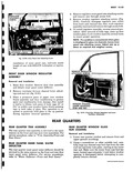
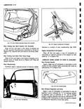
Installation 1 Open door and scribe location of hinge on body 2 Remove bolts fig 10 21 securing hinge to body and remove door assembly 3 To install align hinge within scribe marks and reverse ...
flows through a duct which guides the air into the body poN ATTACHING BOLTS ALT Fig 10 21 Gas Tank Filler Door through a cowl side duct panel air outlet assembly The door |
|
 |
21 Removing Strut Rod Nut Remove the nut washer spacer and grommel from rear end of strut rod fig 3 21 Withdraw strut rod from crossmember bracket Remove rubber grommet spacer washer and nu1 from |
|
 |
21 20 Fig 6C 2 Automatic Transmis 1 Planet Carrier Hub Transmission Output 10 Selective Pinior 2 Rear Selective End Play Spacers 11 Pinion Rear Bec 3 Governor Driven Gear 12 Pinion Shaft ...
Shim 19 Side Bearing Adjusting Sleeve ring and Race 20 Side Bearing Adjusting Sleeve Seal ir Seal 21 Transmission Front Pump Shaft ieal 22 Transmission Turbine Shaft 23 Drain Plug 24 Pinion Shaft at Ring |
|
 |
tube is not bent Should be exactly 90 from body 18 J 17 19 15 16 f 21 20 14 13 12 11 etor Bowl Exploded rge Valve 15 Throttle Valve Kick Lever er Spring ...
Throttle Valve 19 Throttle Valve Retaining Screws Adjusting Screw 20 Fast Idle Adjusting Screw jusfing Screw 21 Throttle Valve Lever and Shaft e Kick Lever H Check choke shaft for wear and choke valve |
|
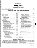 |
Ring Gear and Pinion Bearing Adjustments 6C 20 Ring Gear to Pinion Backlash Adjustment 6C 21 Ring Gear and Pinion Contact Pattern 6C 21 Troubles and Remedies 6C 23 Rear Axle Noise Diagnosis |
|
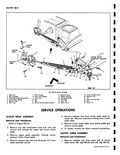 |
swivel V o r 6 7 8 9 ENGINE FRONT MOUNTING BRACKET 4 10 I t 11 21 20 19 18 17 15 16 14 13 12 FORWARD VIEW A Clutch linkage 13 Retainer Strop ...
Clutch Pull Rod Clovis 14 Rubber Bushing 20 Retainer Clip 15 Mounting Bracket 21 Nut 16 Dust Boot 22 Clutch Fork Pull Rod 17 Clovis Pin 23 Bolt 18 Cable Clovis 24 Cotter Pin PERATIONS |
|
 |
necessary adjust the worm bearing adjuster until proper pull is obtained v r r rt Fig 4 21 Lash Adjustment 4 Using the torque wrench turn the gear all the way from one stop ...
screw clockwise to remove all lash between rack and sector teeth Tighten the lock nut fig 4 21 NOTE Be sure the adjustment is not changed while tightening the locknut 6 Again check the torque |
|
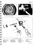 |
STEERING WHEEL Fig 4 9 Steering Wheel Alignment Marks 1 S 3 4 2 t 19 20 21 Fig 4 11 Explode Wormshaft Bearing Adjuster 6 Pitman Arm Nut Lock Nut 7 Pitman Arm Lock ...
Lash Adjuster Screw 19 Ball Nut 14 Lash Adjuster Screw Shim 20 Balls 15 O Ring 21 Ball Guides 16 Side Cover 22 Ball Guide Retainer 17 Side Cover Screws and 23 Ball Guide Retainer |
|
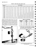 |
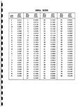
zeros usually preceding the thousandths have been omitted r R f z e z3 17 Fig 6C 21 Installing Pinion Rear Bearings with J 5590 TH SHIM USEAGE CHART Pinion Marking ...
face of pinion gear then install pinion rear bearing using J 5590 as illustrated in Figure 6C 21 Install pinion front bearing in the same manner |
|
 |
Engine Rear Con 9 II gine Lower Shroud and Exhaust Duct 20 Engine Rear Seal il H 21 Engine Roar Sea 10 I houst Duct Door Shaft 22 Engine Roar Shrc 11 I of Washer ...
stop fig 6A 10 4 6 7 8 10 91 11 14 12 e 13 20 19 21 2 33 Sheet Metal components oning 24 Engine front Shroud l M nper Door 25 Engine Front |
|
 |
Gears and Thrust Washers 6D 20 Clutch Keys and Springs 6D 20 Rear Bearing Race Replacement 6D 21 Assembly of Mainshaft 6D 21 Assembly of Transmission 6D 23 Troubles and Remedies 6D 26 Specifications |
|
 |
established unscrew clevis 22 3 turns lengthening rod by 2 9 Tighten pull rod clevis jam nut 21 Line up holes in cable clevis pull rod clevis and clutch fork pull rod idler lever |
|
 |
shown in View C 15 Oil Passage to Main Oil 20 Oil Pump Suction Gallery Left Side 21 Oil Pump Outlet Cavity 16 Oil Pump Outlet 22 Oil Cooler Inlet 17 Oil Enters Ditch Here |
|
 |
21 |
|
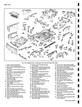 |
Rear Seat Pan Duct Wheelhouse Le 20 Extensions Rear Seat Front Pan Rear 40 Rail Engine Coi 21 Extension Heat Exchqnger Opening 41 Filler Rear End Cover Depression Rig 2 12 23 27 lfl7 |
|
 |
connector 4 Check heater operation BURNER ASSEMBLY Removal Refer to Figures 11 4 11 20 and 11 21 1 Separate five way gang connector on heater case 2 Separate fuel solenoid wire in line connector |
|
 |
weatherstrip from damage then install a twelve to fifteen inch piece of body tape 2 or 21 2 in width over window frame firmly pressing tape to both sides of glass This operation is required |
|
 |
protect paint finish then install a twelve to fifteen inch piece of body tape 2 or 21 z in width over window frame and firmly pressing tape to both sides of glass This is necessary |
|
 |
21 |
|
 |
21 4 APPROX v y Y YY r t Y FLATTEN Y y Y xYxv r x Fig 9 44 Gauge Unit Seal Tight Tool TANK EENBRIER 1Z00 SERIES IDEX Page Fuel Tank |
|
 |
necessary needle seat and gasket may be removed by using a large size screwdriver fig 9 21 It may then be cleaned or replaced as needed 7 Accelerator pump may be removed if necessary Remove |
|
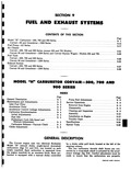 |
controlled ION 9 IAUST SYSTEMS F THIS SECTION Page 9 1 9 15 9 17 Models 9 21 3tation Wagon Models 535 and 735 9 22 9 23 9 25 9 27 9 28 CORYAIR |
|
 |
over terminal and position terminal board 8 Manually rotate washer pump cam through a cycle ratchet rotated 21 teeth to check if pump is operating correctly as explained under pump operation Valve Assembly Remove |
|
 |
thus smaller squirts out of the nozzles When the ratchet wheel has been turned through 3601 or 21 teeth two simultaneous functions occur as TAB O II I SLOT PLUNGER ARM Fig 8 141 Washer |
|
 |
lamp place one test prod lead on armature core and other on each commutator bar fig 8 21 If lamp lights armature is grounded and must be replaced Armature Test for Open Circuit Check |
|
 |
Transmission Case Installed in Holding Fixture J 7896 2 Install two improvised guide pins of approximately 21 2 to 3 in rear pump bolt holes 51 16 18 then install rear pump wear plate |
|
 |
21 I 24 23 22 20 i 9 1 18 i Fig 6E 29 Corvair |
|
 |
Gear 20 Reverse Clutch Front Reaction 6 Front Pump Drive Gear Plate Thick 7 Front Pump Gasket 21 Reverse Clutch Reaction Plates 8 Front Pump Body 22 Reverse Clutch Faced Plates 9 Front Pump Body |
|
 |
side of the transmission case 15 Remove the rear pump and reverse piston assembly mow Fig 61 21 Removing Front Pump Drive Shaft i y 3 4 Fig 61 22 Low Bond Components |
|
 |
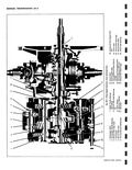
21 22 23 24 25 26 27 r a r Fk r7 1 o 41 40 39 38 37 36 Fig 6E 1 Corvair Powerglide Cross Sectional View |
|
 |
Transmission 9 Clutch Drum Reaction Plate Output 3 Used 20 Reverse Piston 10 Clutch Drum Faced Plate 21 Reverse Piston Return Spring 2 Used 17 Used 11 Clutch Piston Return Spring 15 Used 22 Rear |
|
 |
Reverse Washer 15 Second and Third Speed Clutch inshaft Bearing 16 First and Reverse Shift Fork 21 Monum inshaft 17 Manual Shift Shaft Finger 22 Clutch |
|
 |
bearing bores 1 Differential Carrier 3 Speed 20 Pinion Rear Set 2 U Bolt Nuts and Lockwashers 21 Pinion Rear Set 3 U Joint Yoke 22 Pinion Rear Set 4 U Bolts 23 Cover Gasket |
|
 |
IBOARD FORWARD s Linkage Exploded 14 Retainer Spring 21 Cotter Key 15 Flat Washer 22 Swivel 16 Lockwasher 23 Ball Stud 17 Nut 24 Lock Nut 18 Clevis Assembly 25 Items to be Lubricated before |
|
 |
Notch on piston top must be installed toward the front of engine flywheel end on both banks 21 With piston assemblies in the cylinder bores place connecting rod bearing inserts in place on connecting rods |
|
 |
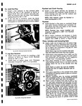
bearing and press assembly in place to a height of 4 520 as shown in Figure 6A 21 4 530 NOTE Do not press on bearing inner race Installation 1 Wipe crankcase gasket surface with |
|
 |
deep socket BLOWER BEARING HUB ASSEMBLY 4 520 4 530 CRANKCASE COVER GASKET RAIL Fig 6A 21 plower Bearing and Crankcase Cover Assembly CORVAIR SHOP MANUAL |
|
 |
will b affected if shims are altered See Section 3 Suspension for rear toe in adjustment 21 Lower the power train gradually and watch for possible interference at rear mount and left rear lower control |
|
 |
Removal 5 19 Inspection 5 19 Installation 5 20 Specifications 5 20 Troubles and Remedies 5 21 Special Tools 5 22 SCRIPTION to meet the duty requirements of the Commercial and Sportswagon The brakes |
|
 |
Load Adjustment 1 With worm bearing pre load properly adjusted rotate steering gear to center of travel 21 z turns from stop 2 Turn lash adjusting screw into gear case until light contact is felt |
|
 |
universal joint U bolts Remove the U bolts t 1 lti J rv 1 r y 21 Fig 3 28 Removing Backing Plate Attaching Nuts 8 Remove the bolt lockwasher and flat spacer from |
|
 |
shaft fully to rear of case until it engages interlock Secure shift fork shaft with roll pin 21 Install remaining detent ball spring nylon washer and cap in 3 4 detent channel at left rear |
|
 |
Lubriplate or equivalent to channel portions of lid support as indicated by 1 in Figure 2 21 LUBRICATE WHEN ACCESS TO PARTS IS AVAILABLE Door Outside Handle Apply a light coat of Lubriplate or equivalent |
|
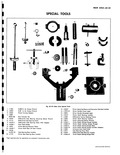 |
Installer 19 J 0972 Pinion Adjusting Sleeve Wrench 20 J 6266 1 Pinion Depth Setting Gauge Cylinder 21 1 6266 19 Pinion Depth Setting Gauge Plunger 22 J 6266 5 Pinion Depth Setting Gauge Plate |
|
 |
imbedding in the bleeder holes during braking action 4 Check piston fit in cylinder bore fig 5 21 The clearance between piston and wall of the cylinder should be from 001 005 Assembly Whenever |
|
 |
disconnected or connected as described below for removal or installation of the power train fig 6 21 1 Clutch return spring at clutch housing and pull rod idler lever 2 Clutch cable retainer at engine |
|
 |
cylinder metal over both edges of the retainer ends using a suitable staking tool at right angles 21 32 DIA REAR BUMPER LIFT HOLES |
|
 |
Reconditioning 5 14 Cleaning b 14 Installation 6 14 Specifications 5 14 Troubles and Remedies 5 21 Special Tools 5 22 CORVAIR SHOP MANUAL |
|
 |
with SAE 80 Multipurpose Gear Lubricant Complete refills require a total of 4 9 pints lubricant approximately 21 2 pints for each unit SHIFT LINKAGE ADJUSTMENT After any service operation in which the shift control |
|
 |
l7fliY s r s 14 15 6 17 l 18 19 20 21 22 23 24 25 26 27 28 29 30 31 32 33 34 37 36 35 I Transmission Cross Sectional View |