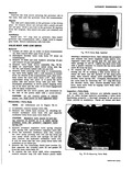
| Book |
Page |
Context |
 |
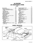 |
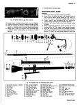
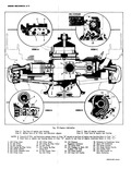
Ducts and Outlets 15 19 Blower and Air Inlet Assembly 15 19 Control Panel Assembly 15 21 Control Panel 15 21 Fan Switch 15 21 Air Selector Switch 15 21 Resistor Control Cables and Wiring ...
21 Compressor 15 21 Minor Repair Procedures 15 23 Major Repair Procedures 15 26 Compressor Belt Tension Adjustment 15 35 Condenser 15 35 Engine Access Procedure 15 35 Receiver Dehydrator 15 35 Collision Procedure |
|
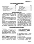 |
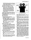
Maintenance and Adjustments 7 lg Lubrication 7 19 Shift Linkage Adjustment 7 ig Service Operations 7 21 Service Operations Transmission in Vehicle 7 21 Gearshift Lever Assembly 7 21 Shift Control Rod 7 21 Service ...
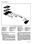
Operations Power Train Removed from Vehicle 7 21 Disassembly of Transmission 7 gl Disassembly of Mainshaft 7 22 GENERAL The Corvair four speed transmission fig 7B 1 is of the helical gear constant mesh type |
|
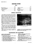 |
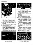
Installation 6Y 19 Coil Replacement 6Y 20 Ignition Switch Replacement 6Y 20 Spark Plugs 6Y 21 Cleaning and Regapping 6Y 21 Installation 6Y 21 SCRIPTION f y Fig 1i Distributor Spark Curve Spark plugs should |
|
 |
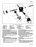
shim s selected Step 1 rear face 1 pinion 1 install pinion 1 p 1 Figure 21 Install pinion front bearing the same manner 1 PEWON DEPTH SHIM USAGE CHART ti 11 Reading ...
21 1 261 21 Pinion Front Bearing Race Replacement 1 Remove old race with a punch as illustrated fig 22 automatic transmission models ls it is necessary to remove the seaL 2 Install new race |
|
 |
SHAFT SHAFT SHAFT BEARING RETAINE R RING r CLUTCH SELECTIVE SHAFT SNAP RING RING Fig 7B 21 Clutch Gear and Bearing Snap Rings tion With the interlock notches aligned the reverse shifter head shaft ...
seats against front of case 15 Retain clutch gear in bearing with selective snap ring fig 7B 21 With proper snap ring installed maximum end play between bearing and snap ring will ...
Install small snap ring in inner diameter of clutch gear fig 7B 21 This snap ring acts as a bottoming stop for the input clutch shaft 17 Prior to installing the 1 2 shift fork |
|
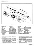 |
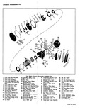
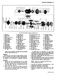
Selective 19 Clutch Gear Bearing 3 5 Thrust Washer 20 Front Cover Gasket b Second Speed Gear 21 Front Cover 7 Mairahaft 22 Front Cover Mounting Bolt 3 8 First and Reverse Sliding Gear ...
21 2 r 24 v l i 36 37 23 tission Exploded View 0 Detent B611 44 Reverse Idler Gear Shaft Lock Detent Spring Pin I Roll Pin 45 Countergear Shaft Interlock 46 Countergear Front ...
rollers in each end The grease will hold the rollers in place while installing fig 7A 21 9 Insert J 5777 in countergear 10 Apply grease to bearing thrust washers and countergear thrust washer |
|
 |
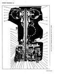
21 30 w4 Ilk 6 7 10 6 A 8 9 013 11 12 014 LALIS 15 4 28 27 4 Fig 3s Starti 1 Drive Housing 6A Solenoid Return 11 Th 2 Shift Lever ...
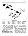
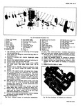
field coils the component parts should be cleaned and inspected as described below 19 20 r1 21 22 19 24 2 22 01 23 20 w 24 16 17 18 26 25 Motor Parts Layout ...
Frame 23 Brushes toiner 19 Brush Springs 24 Screws rerrunning 20 Washer 25 Field Coils itch Assembly 21 Insulated Brush 26 Insulators mature Holders 27 Pole Shoes 28 Screws Field coils need be removed only |
|
 |
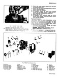
Connect battery positive cable 14 Install air cleaner assembly then install spare tire Left Shield Fig 21 j Removal 1 Remove bolts attaching left side of upper shroud and left shield to cylinder head ...
block of wood or a hammer handle 4 Connect ground strap if so equipped Right Shield Fig 21 Removal 1 Remove spare tire then remove bolts attaching right side of upper shroud and right shield ...
equipped remove screw from ground strap 5 Disconnect seal from flange of right shield O y Fig 21 Engine Shields C 1QV IQ fXfM Y Alll |
|
 |
Distributor Installed 14 15 16 17 2 18 4 19 6 7 1 8 9 10 r 21 12 23 1 wlr3 Fig 6i Distributor Exploded View 1 Cap 13 Housing 2 Rotor 14 Weight ...
Assembly 8 Condenser 19 Mainshaft Assembly 9 Breaker Plate Assembly 20 Washer 10 Cam Lubricator 21 Thrust Washers 11 Vacuum Advance Linkage Boot 22 Roll Pins 12 Vacuum Control Assembly 23 Drive Gear CLEANING |
|
 |
21 2 Fig 8 Exploded 1 Wormshaft Bearing 6 Pitman Arm Nut Adjuster Locknut 7 Pitman Arm Lock 2 Wormshaft Bearing Washer Adjuster 8 Pitman Shaft Seal 3 Wormshaft Bearing 9 Pitman Shaft Bushing ...
Lash Adjuster Screw 19 Ball Nut 4 Lash Adjuster Screw Shim 20 Balls 5 O Ring 21 Ball Guides 6 Side Cover 22 Ball Guide Retainer 7 Side Cover Screws and 23 Ball Guide Retainer |
|
 |
21 23 20 22 19 18 Fig 7E 29 Corvair Powe l Front Pump Mounting Bolts 16 Low Band Apply Strut j 2 Front Pump Cover 17 Planet Carrier Assembly 3 Front Pump Seal Ring ...
Reverse Clutch Front 5 Front Pump Driven Gear Reaction Plate Thick b Front Pump Drive Gear 21 Reverse Clutch ReactionPlc tes 7 Front Pump Body 22 Reverse Clutch Faced Plates 8 Front Pump Gasket |
|
 |
21 v y s 22 S 24 1 11 6 7 4 5 2 3 11 Remove the pump discharge needle valve and power enrichment needle valve 12 Remove the idle mixture adjusting needle ...
Exploded View 14 Needle 20 Vacuum 15 Float Assembly Diaphragm 16 Fast Idle Rod 21 Retainer Screws 17 Choke Shaft 22 Choke Valve Lever Screw 23 Choke Shaft and 18 Choke Shaft Outer Lever Lever |
|
 |
21 I 4 I Fig 7E 1 Corvair Pow erglide 1 Valve Body to Transfer Plate 7 Low Drive Valve Inner S I nng cttaehingSerews 4 8 Low Drive Valve Outer Spring 2 Transfer Plate ...
Valve 15 Re a r Pump Priming Ball 20 SPr eaaure Regulator Valve 16 Hydraulic Modulator Valve 21 Detent Valve Assembly 22 Throttle Valve Spring 17 F ydroulic Modulator Valve 23 Throttle Valve Booster Valve |
|
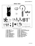 |
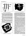
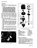
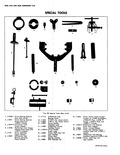
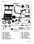
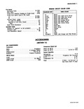
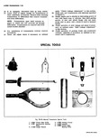
21 23 24 Fig 61 Air Con 1 J 8393 Charging System 2 J 5453 Go oqgles 3 J 9459 90 Gauge Line Adapter 4 J 5420 Gauge Line Adapter 5 J 6084 Leak Detector ...
Plate Assembly Installer 19 J 9401 Hub and Drive Plate Assembly Remover 20 J 9392 Seal Remover 21 J 9393 Seal Seat Remover 22 J 9398 Pulley Bearing Remover 23 J 9481 Pulley and Bearing |
|
 |
21 20 19 Fig 2 Automatic 1 Planet Carrier Hub 7 Vent Transmission Output 8 Pinion Gear 2 Rear Selective End Play Spacers 9 Selective Pinion Depth Shir 3 Governor Driven Gear 10 Pinion Rear ...
Side Bearing Adjusting 15 Pinion Shaft Seal Ring Sleeve seal 16 Stator Shaft O Ring Seal 21 Transmission Front Pump e 17 Differential Carrier Filler Plug shaft 18 Side Bearing Adjusting Sleeve 22 Transmission Turbine |
|
 |
body as viewed in Figure 7E 11 6 Place throttle valve spring 22 and detent valve assembly 21 in throttle valve bore then depress detent valve assembly 21 and secure to valve body by tapping |
|
 |
qnnnl wn All I 111 i l h 20 21 22 23 24 25 26 27 Fig 30 Six Cylinder C 1 Rear Hood 11 Front Head to Shelf 2 Rear Mead to Shelf ...
Drive 29 Cylinder Assembly Plate Assembly 30 Shaft seal Z0 Oil Pump Gears 31 Shaft Seal Seat 21 Mainshaft Bearing Rear O Ring 22 Oil Inlet Tube O Ring 32 Shaft Seal Seat |
|
 |
later reference when determining impeller end clearance 6 7 8 s e 0 C t t 21 22 rger Exploded View 12 Mating Ring Washer 18 Impeller 13 Oil Seal Assembly 19 Impeller Special Washer ...
Ring Seal 20 Impeller Nut 15 Seal Retaining Ring 21 Compressor Housing 16 Shaft Sleeve Gasket 17 Impeller Shim 22 Compressor Housing 4 Determine bearing to housing end play and select the proper shim |
|
 |
Pinion Backlash Adjustment 4 19 Ring Gear and Pinion Contact Pattern 4 19 Positraction Differential 4 21 Positraction Preload Check On the Vehicle 4 21 Disassembly 4 22 Inspection 4 22 Assembly 4 23 Clutch |
|
 |
21 23 y t 22 1 s i 24 y V W 6 8 1 2 s 4 5 7 C XZW Fig 8 Carburetor Bad 1 Pump Lever 8 Idle Mixture Adjusting Retaining Screw ...
Valve 19 Venturi Cluster Lever and Shaft Gasket 14 Throttle Valve 20 Main Well Insert Retaining Screws 21 Main Metering Jet 15 Throttle Valve 22 Power Enrichment 16 Fast Idle Cam Needle Mounting Screw |
|
 |
Housing Seal 6 20 Engine Rear Housing 6 24 Distributor Drive Gear and Fuel Pump Eccentric 6 21 Valve Lifters Valve Train Components 6 2Cylinder Head Assemblies 6 2Valve Springs and or Valve Stem ...
Seals 6 21 Connecting Rod Bearings 6 24 Piston Ring and or Cylinder Gasket 6 2 Camshaft 6 2 Measuring Lobe Lift At Push Rod 6 2 Engine Assemblies Power Train 6 2 Repair Procedures |
|
 |
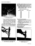
21 3 4 1 1 18 30 35 23 28 Foot Pounds i a AMEML Fig 20 Hose Clamp and Fitting Indications of expansion valve trouble provided by the Performance Test are as follows Valve ...
Carefully with a sharp knife make an angle cut in the hose as shown in Figure 21 This should loosen the hose so that it may be worked off the fitting CAUTION Use extreme care |
|
 |
UTOOLS 0 4 5 6 7 11 12 0 0 0 17 18 19 20 21 tools Rear Suspension 11 J 8614 3 Drive Spindle Flange Remover Power Screw 12 J 21836 Drive Spindle Spacer ...
Drive Spindle Outer Bearing Installer 20 J 7817 Drive Spindle Inner Bearing Cup Installer 21 J 21Q58 7 Torque Arm Bushing Adapter CORVAR SHOP MANUAL |
|
 |
Pulley Bearing Valve Plate Retainer Ring 20 Front Suction 7 Pulley Bearing Reed Valve 8 Pulley 21 Discharge Crossover 9 Coil Housing Tube Front O Retainer Ring Ring and Spacer 10 Coil Housing 22 Moinshaft ...
21 20 19 ompressor Exploded View 26 Suction Crossover Cover 42 Discharge Crossover 27 Drive Key Tube Rear 0 Ring 28 Discharge Crossover Tube and Spacer 29 Piston Ring 43 Rear Suction 30 Piston Front |
|
 |
Reverse Idler Gear Shaft 6 4th Blacker Ring 20 Reverse Idler Gear 7 3 4 Shift Collar 21 Rear Bearing Retainer 8 3rd Blacker Ring 22 First Gear 9 Third Gear 23 Rear Bearing Selective ...
Shaft Defent Ball and Spring I 12 13 14 15 16 17 18 19 20 w 4 21 |
|
 |
21 Rear End Lighting 3 Untape switch wire from body wiring harness and separate switch wiring connectors 4 Disconnect switch wiring from body attaching clips and remove switch assembly from transmission 5 Install new switch ...
insert new bulb 3 Snap lamp socket into mounting bracket TAIL STOP DIRECTIONAL AND BACKING LAMPS Fig 21 To Replace Bulb i Unsnap bulb socket from underside of lamp housing in engine compartment 2 Remove |
|
 |
21 ols Rear Axle Side 16 J 6266 Pinion Setting Depth Gauge sr Consists of J 6266 18 Adapters torque wrench J 6266 25 Plug J 6266 19 torque wrench Gouge J 6266 5 Plate ...
Front Oil Handle r 20 J 8359 Differential Side Bearing Installer UsedwithJ 7079 2 Hdl iller 21 J 8448 1 Pinion Shaft Rear Oil r Set Seal Installer CORVAR 5110P MuNUu |
|
 |
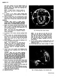
shaft out of the upper end of the mast jacket remove the cap screw previously installed Fig 21 5 ing SF I Fig 22 Directional Housing Guide Position and allow the locking rod to slide ...
jacket into place 2 With the spring stop and both snap rings in place as in Figure 21 Insert steering shaft into mast jacket from the upper end 3 Install the lower bearing into |
|
 |
Steering Shaft Nut 19 Upper Bearing Plate 9 Steering Shaft Washer 20 Upper Bearing 10 Stop Stud 21 Directional Switch 11 Screws 22 Lever Screw 7 Install battery ground cable TELESCOPING MAST JACKET Removal ...
lower bracket It may be necessary to rotate the mast jacket slightly to allow the 19 20 21 |
|
 |
Remove the front pump cover fig 7E 20 then re move the pump shaft fig 7E 21 Use care in pump removal not to damage bushings in front pump body and turbine shaft with |
|
 |
ANGULAR CUT Fig 21 Recommended Hose Removal Procedure Leaks at O Ring Connection 1 Check the torque on the fitting and if too loose tighten to the proper torque Always use a backing wrench |
|
 |
Flat Wound A rox 4 1 21 32 1 32 CORVAR SHOP MANUAL |
|
 |
Clutch Drum Reaction Plate mission Output 3 Used 20 Reverse Piston 10 Clutch Drum Faced Plate 21 Reverse Piston Return Spring 2 Used 17 Used 11 Clutch Piston Return Spring 22 Rear Pump Driven Gear |
|
 |
shaft fully to rear of case until it engages interlock Secure shift fork shaft with roll pin 21 Install remaining detent ball spring nylon washer and cap in 3 4 detent channel at left rear |
|
 |
Inspection The most frequent causes of carburetor malfunction 12 13 14 15 16 17 18 19 21 |
|
 |
Valve Guide Cleaner I 19 J 8520 Indicator Set Camshaft Lobe 20 J 8001 Indicator Set Universal 21 J 8087 Indicator Set C linder Bore 22 J 1264 Torque Wrench |
|
 |
coat surfaces lightly with Molykote or its equivalent Install the right cylinder head in the same manne 21 Install muffler hanger and r e a r shrouds the using new seals install oil cooler |
|
 |
equipped 5 Install ignition coil and bracket then install spare tire Rear Center Shield Fig 21 I NOTE The rear center shield is two pieces The engine seal is connected to the upper half |
|
 |
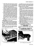
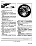
completing installation make certain the actuator lever functions easily by hand operating the self adjusting feature fig 21 16 Follow the above procedure for all brakes 17 Adjust the service brakes as outlined below then |
|
 |
installation is made 12 If old brake pull back return springs are nicked i a Fib 21 Checking Operation of the Actuating Lever CORVAR 5110P MANUAL |
|
 |
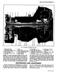
View A 14 Oil i Pump Inlet 20 Oil Pump Suction 15 Oil Passage to Main Oil 21 Oil Pump Outlet Cavity 16 utlet 23 Oil from Cooler |
|
 |
housing and discard gasket 20 Remove the oil pick up screen tube bracket and short crankcase bolt 21 Disconnect flywheel housing from Tool J 8280 then remove crankcase assembly and flywheel housing from engine stand |
|
 |
hammer handle 3 Install all retainer attaching screws finger tight then tighten screws securely Front Shield Fig 21 Removal i Disconnect battery positive cable 2 Remove spare tire then remove |
|
 |
shroud then install spare tire 20 If necessary fill engine with oil fill transmission and fill axle 21 Start engine check fog leaks and perform necessary adjustments ROCEDURES I 75 3 HOLES HOLE |
|
 |
driver between its head and the surface of the main valve body then remove detent valve assembly 21 and throttle valve spring 22 Complete disassembly of the valve body by removing the E ring |
|
 |
21 22 23 24 25 26 27 SIMOWMEME |
|
 |
CAUTION As liquid R 12 enters an area of atmpspheric pressure its temperature will immediately drop to 21 7 F Be sure to direct the outlet of the unit or units being flushed into |
|
 |
being performed the specifications should be lowered by 1 inch Example at 5000 ft elevation only 21 to 23 inches of vacuum can normally be obtained Whenever the air conditioning system is opened |
|
 |
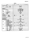
WASHER PUMP Number of squirts at full pressure x Pressure psi 11 1 Coil Resistance ohms 21 CC SEC AIR CONDRIONIN s Compressor Make Frigidair Type 6 Cylinder AXIAI Displacement 10 8 Cu In Rotation |
|
 |
Check shift linkage operation and adjust if necessary as outlined under Shift Linkage Adjustment in this Section 21 Check operation of parking brake and accelerator controls adjusting if necessary as outlined in Sections |
|
 |
transparent and colorless in both th gaseous and liquid state It has a boiling point of 21 7 below zero and therefore at all normal temperature and pressures it will be a vapor The vapor |
|
 |
Just remember any R 12 liquid that you can touch or that touches you is at least 21 7 F below zero The eyeballs can t take much of this temperature If R 12 liquid |
|
 |
Linkage Adjustment in this section 20 Refill axle and transmission with lubricant specified in S tion 0 21 Instzl engine seal to shields by lubricating groove of seal Iwith liquid soap or silicone then while |