Jeep Parts Wiki | Ford Parts Wiki
Home | Search | Browse | Marketplace | Messages | FAQ | Guest
|
Body Service Manual August 1964 |
|
Prev

 Next
Next
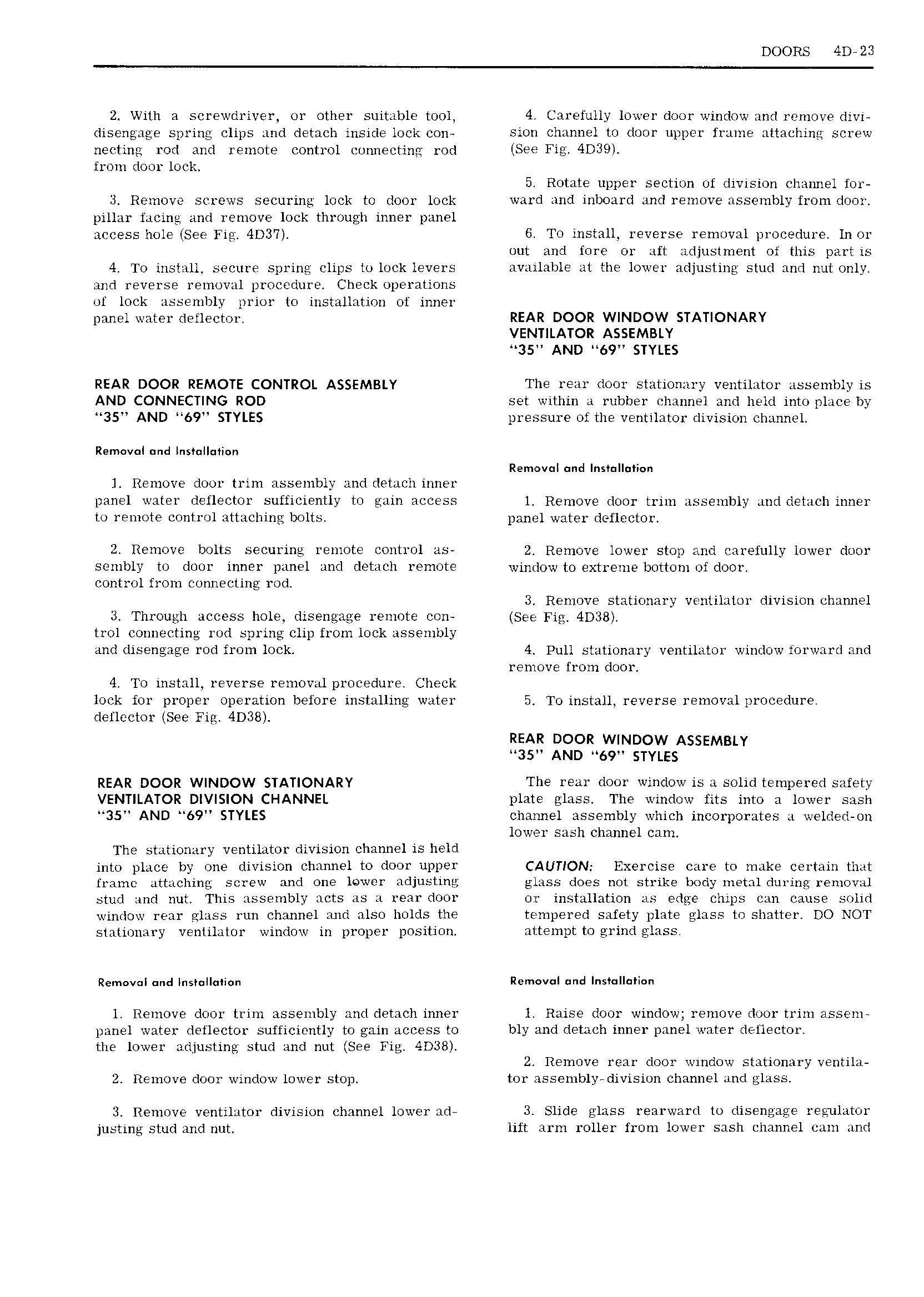
DOORS 4D 23 2 With a screwdriver or other suitable tool 4 Carefully lower door window and reniove divi disengage spring clips and detach inside lock con sion channel to door upper frame attaching screw necting rod and remote control connecting rod See 4D39 from door lock 5 Rotate upper section of division chaiuiel for Remove screws securing lock to door lock ward and inboard and remove assembly from door pillar facing and remove lock through inner panel access hole tSee 4D3 7 G To install reverse removal procedure ln or out and fore or aft adjustment of this part is 4 To install secure spring clips to lock levers available at the lower adjusting stud and nut only and reverse removal procedure Check operations of lock assembly prior to installation of inner panel water deflector REAR DOOR WINDOW STATIONARY VENTILATOR ASSEMBLY 35 AND 69 STYLES REAR DOOR REMOTE CONTROL ASSEMBLY The rear door stationary ventilator assembly is AND CONNECTING ROD set within a rubber channel and held into place by 35 AND 69 STYLES pressure of the ventilator division channel Removal mid lns II i n Removal mid Insmllntion l Remove door trim assembly and detach inner panel water deflector sufficiently to gain access l Remove door trim assembly and detach inner to remote control attaching bolts panel water deflector 2 Remove bolts securing remote control as 2 Remove lower stop and carefully lower door sembly to door inner panel and detach remote window to extreme bottom of door control from connecting rod 3 Remove stationary ventilator division chumiel 3 Through access hole diseneace remote con See Fig 4D38 trol connecting rod spring clip from lock assembly and disengage rod from lock 4 Pull stationary ventilator window forward and remove from door 4 To install reverse removal procedure Check lock for proper operation before installing water 5 To install reverse removal procedure deflector See Fig 4D38 REAR DOOR WINDOW ASSEMBLY 35 AND 69 STYLES REAR DOOR WINDOW STATIONARY The rear door window is a solid tempered safety VENTILATOR DIVISION CHANNEL plate glass The window fits into a lower sash 35 AND 69 STYLES channel assembly which incorporates a welded on lower sash channel cam The stationary ventilator division channel is held into place by one division channel to door upper CAUTION Exercise care to make certain that frame attaching screw and one lower adjusting glass does not strike body metal during removal stud and nut This assembly acts as a rear door or installation as edge chips can cause solid window rear glass run channel and also holds the tempered safety plate glass to shatter DO NOT stationary ventilator window in proper position attempt to grindglass Rem v l und Ins II i n Rem v l nd lns II ti n l Remove door trim assembly and detach inner l Raise door window remove door trim assem panel water deflector sufficiently to gain access to bly and detach inner panel water detlector the lower adjusting stud and nut See Fig 4D38 2 Remove rear door window stationary ventila 2 Remove door window lower stop tor assembly division channel and glass Remove ventilator division channel lower ad 3 Slide glass rearward to disengage regulator justing stud and nut lift arm roller from lower sash channel cam and

 Next
Next