Jeep Parts Wiki | Ford Parts Wiki
Home | Search | Browse | Marketplace | Messages | FAQ | Guest
|
Body Service Manual August 1964 |
|
Prev

 Next
Next
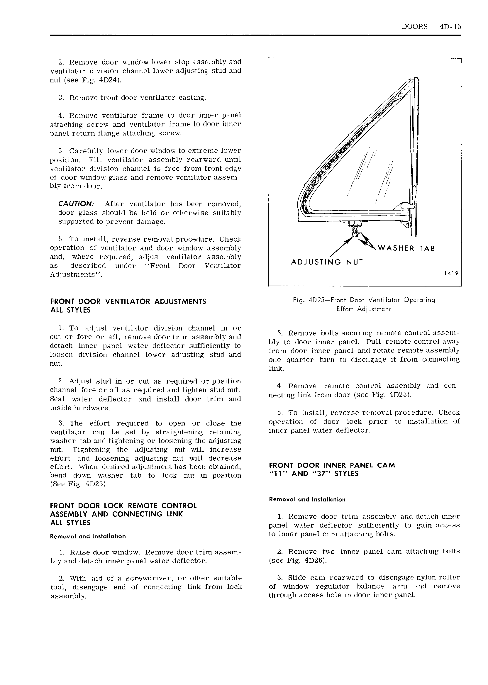
DOORS 4D l5 2 Remove door window lower stop assembly and ventilator division channel lower adjusting stud and nut see 4D24 3 Remove front door ventilator casting 4 Remove ventilator irame to door inner DHHGI attaching screw and ventilator frame to door inne1 panel return flange attaching screw 5 Carefully lower door window to extreme lower fi position Tilt ventilator assembly rearward until gy ventilator division channel is free from front edge 4 if jg of door window glass and remove ventilator assem Q Zfl bly from door CAUTION After ventilator has been removed door glass should be held or otherwise suitably A 7 supported to prevent damage 6 To install reverse removal procedure Check 7 operation of ventilator and door window assembly WASHER TAB and where required adjust ventilator assembly as described under Front Door Ventilator ADJUSTING NUT Adjustments Nl 9 FRQNT DQQR VENHLATOR ADJUSTMENTS Fig 4D25 From Door x entilmcr Opemring ALL STYLES Effort Adgustment l To adjust ventilator division channel in or out Or fore Or aft remove dOO1 trim assembly and 3 Remove bolts securing remote control assem lPtH 1h inner panel water deflector Sufficigiitiy to Ply tOl l0 iT 1 n 1 panil TU llt I 11OTE cgmtrol awuiy loosen division channel lower adjusting stud and hom Om Inner Pane fmt 10 1 l mo E A b m nut one quarter turn to disengage it from connecting I link 2 Adjust stud in or out as required or position 4 R t t 1 M r channel fore or aft as required and tighten stud nut Epmsi len 9 CON 1 F dm com Seal water deflector and install door trim and n clmb m mm DOT bee 1 ll t t mbxg MIUHIE 5 To install reverse removal procedure Check 3 The effort required to open or close the operation of door lock prior to installation of ventilator can be set by straightening retaining m Yl i 1 3t l d H CtOY washer tab and tightening or loosening the adjusting nut Tightening the adjusting nut will increase effort and loosening adjusting nut will decrease effort When desired adjustment has been obtained FRONT DOOR INNER PANEL CAM bend down washer tab to lock nut in position HHH AND 37 STYLES See Fig 4D25 Removal nd Ins II ri n FRONT DOOR LOCK REMOTE CONTROL ASSEMBLY AND CONNECTING LINK l Remove door trim assembly and detach inner ALL STYLES panel water deflector sufficiently to gain access Remmmj and j S i to inner panel cam attaching bolts l Raise door window Remove door trim assem 2 Remove two inner panel cam attaching bolts bly and detach inner panel water deflector see Fig 4D26 2 With aid of a screwdriver or other suitable 3 Slide cam rearward to disengage nylon roller tool disengage end of connecting link from lock of window regulator balance arm and remove assembly through access hole in door inner panel

 Next
Next