Jeep Parts Wiki | Ford Parts Wiki
Home | Search | Browse
|
Body Service Manual August 1964 |
|
Prev

 Next
Next
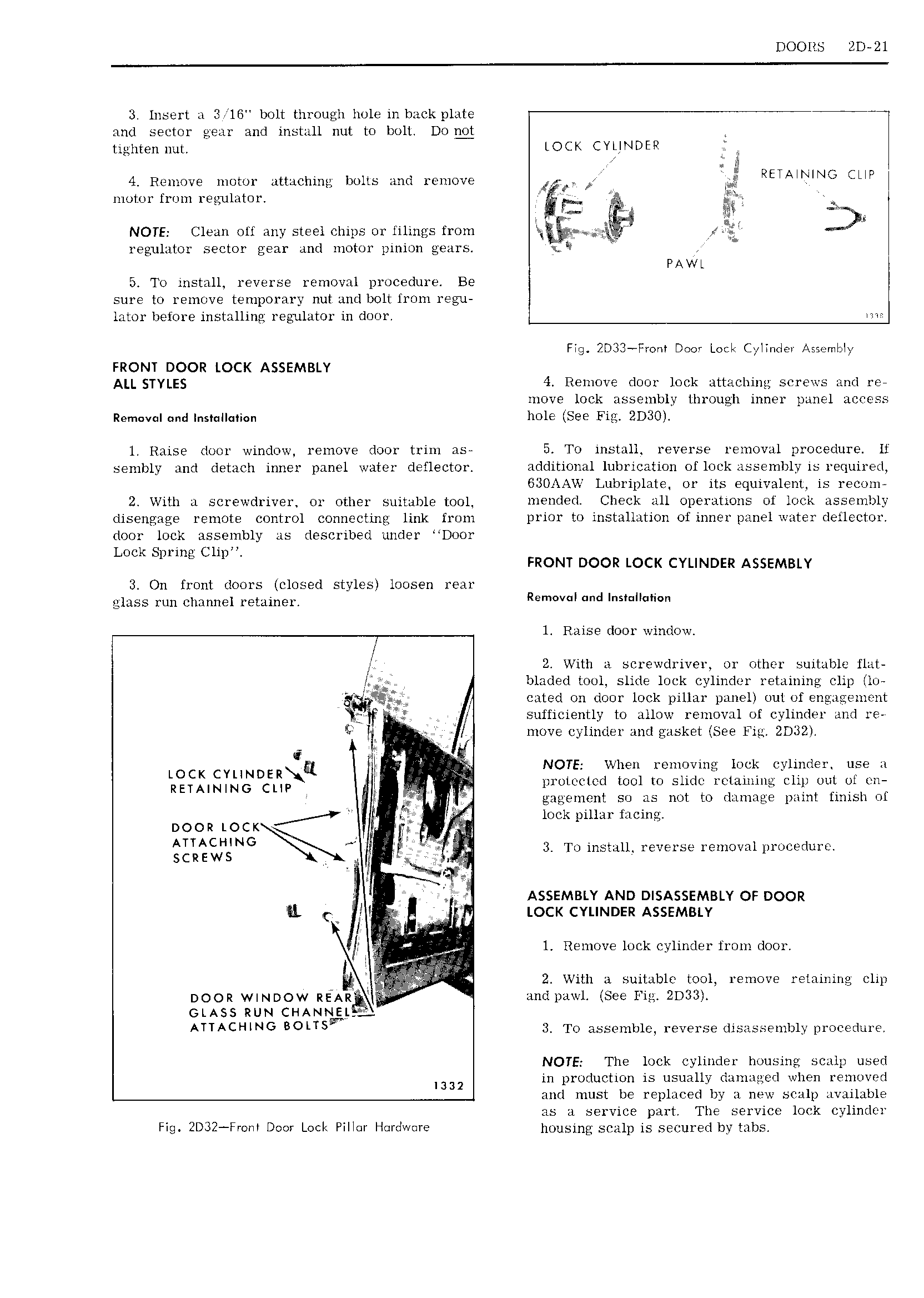
DOORS ED 21 3 Insert a 3 16 bolt through hole in hack plate and sector gear and install nut to bolt Dog tighten nut LOCK CYLINDER 4 Remove motor attaching bolts and remove J M RETAWING CMP l motor from regulator I w V II2 4 v It fw NOTE Clean oil any steel chips or lilings from wl I gy 4 g regulator sector gear and motor pinion gears PAWL 5 To install reverse removal procedure Be sure to remove temporary nut and bolt lrom regu lator before installing regulator in door me Fig 2D33 Fm r Dom LMI C II Ie A emI Iv FRONT DOOR LOCK ASSEMBLY ALL STYLES 4 Remove door lock attaching screws and re move lock assembly through inner panel access Rem v l und Ins II 1i n hole See Fig 2D30 1 Raise door window remove door trim as 5 To install reverse removal procedure lf sembly and detach inner panel water cleflector additional lubrication of lock assenibly is required 630AAW Lubriplate or its equivalent is recom 2 With a screwdriver or other suitable tool mended Check all operations of look assembly disengage remote control connecting link from prior to installation of inner panel water deilector door lock assembly as described under Door Lock Spring Clip FRONT DOOR LOCK CYLINDER ASSEMBLY 3 On front doors closed styles loosen rear glass run channel retainer Re v d i 1 Raise door window It 2 With a screwdriver or other suitable flat bladed Loul slide lock cylinder retaining clip I lo g 4 cated on door lock pillar panel out of eng igem nt sufficiently to allow removal of cylinder and re Ii p inove cylinder and gasket See Fig 21332 LOCK CYLINDERQQ II t rwhen removingv eylinder use a RETAINING CUP I piotuatcd tool to slide retaining clip out ut en g I r gagement so as not to damage paint finish of I Y 2 i t DOOR LOCK 27 Q G Q lonh pillu firing Qglii H NGk N 1 3 To install reverse removal procedure 1 1 tl ASSEMBLY AND DISASSEMBLY OF DOOR LL l rv LOCK CYLINDER ASSEMBLY I al fr 1 Remove lock cylinder from door I I if i4 I Et 2 With 1 suitable tool remove retaining clip DOOR WINDOW REAR 4 and pziwl See Fig ZD33 GLASS RUN CHANN j I 9 L ATTACHING BOLTS 3 To assemble reverse disassembly procedure NOTE The lock cylinder housing scalp used I332 in production is usually daniaged when removed and must be replaced by a new scalp available as a service part The service lock cylinder Fig 2D32 Fmm Door Lock PiII r Hqrdwure housing scalp is secured by tabs

 Next
Next