Jeep Parts Wiki | Ford Parts Wiki
Home | Search | Browse
|
Body Service Manual August 1964 |
|
Prev

 Next
Next
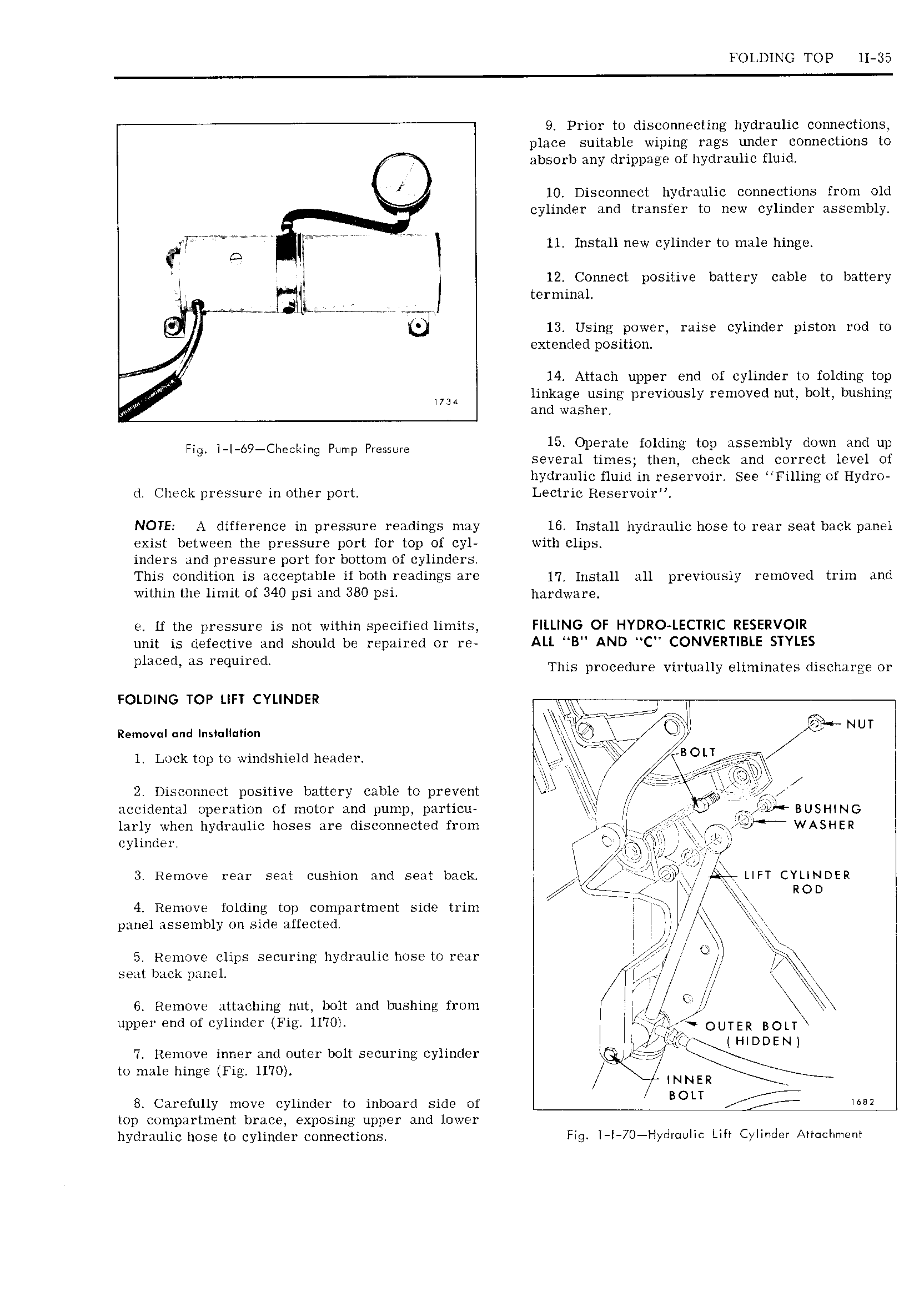
FOLDING TOP 11 35 9 Prior to disconnecting hydraulic connections place suitable wiping rags under connections to absorb any drippage of hydraulic fluid 10 Disconnect hydraulic connections from old cylinder and transfer to new cylinder assembly qpvw I I N 11 Install new cylinder to male hinge 2 y 12 Connect positive battery cable to battery I A I terminal mid a F an 13 Using power raise cylinder piston rod to I extended position 14 Attach upper end of cylinder to folding top w UU linkage using previously removed nut bolt bushing w and washer Fig b9 ChScking Pump Pressure 15 Operate folding top assembly down and up several times then check and correct level ot hydraulic fluid in reservoir See Fil1ing of Hydro d Check pressure in other port Lectric Reservoir NOTE A difference in pressure readings may I6 Install hydraulic hose to rear seat back panel exist between the pressure port for top of cyl with clips inders and pressure port for bottom of cylinders This condition is acceptable if both readings are 17 Install all previously removed trim and within the limit of 340 psi and 380 psi h pdw8p e lf the pressure is not within specified limits FILLING OF HYDRO LECTRIC RESERVOIR unit is defective and should be repaired or re ALL B AND C CONVERTIBLE STYLES p1ucEd ds F quu d This procedure virtually eliminates discharge or FOLDING TOP LIFT CYLINDER W I nemwanana I S II a jjT jI 4 LII III 1 NUI L 7 BOLT l Lock top to windshield header V gx V 3 I H at e E I 2 Disconnect positive battery cable to prevent 4 r g accidental operation of motor and pump particu M CD iL nusnmg larly when hydraulic hoses are disconnected from 1 WASHER cvl ler Q VI I I 1 I I EI Ip UI 3 Remove rear seat cushion and seat back I F LIZ LIFT CYLINDER r 1 e ROD I 4 Remove folding top compartment side trim I Icp 5 I J l pane assembly on side affected 1 I 5 Remove clips securing hydraulic hose to rear U I U I seat back panel V M y NM f 6 Remove attaching nut bolt and bushing from I i AI k I i upper end of cylinder Fig 1I TOI jr r OUTER BOLT L j J Qj j HIDDEN 7 Remove inner and outer bolt securing cylinder I Aifgij X to male hinge Fig 1170 7L NNER 8 Carefully move cylinder to inboard side of I BOLT IM top compartment brace exposing upper and lower hydraulic hose to cylinder connections Fig I I 70 I Iydr uIIc Life Cylinder Attachment

 Next
Next