Jeep Parts Wiki | Ford Parts Wiki
Home | Search | Browse
|
Body Service Manual August 1964 |
|
Prev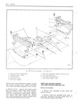

 Next
Next
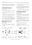
SEATS lH 7 3 Detach horizontal and vertical drive cables from adjuster to be removed 4 A 4 Remove adjustereto seat bottom frame front and rear attaching bolts and remove adjuster from seat assembly Fig lH6 B V E J lx 5 To install seat adjuster assembly reverse fo removal procedure Make sure adjuster track cover Q 31 supports are installed between adjuster and seat F it r V n irame Black drive cable attaches to horizontal g lr 33 rV gp actuator Fig 1H6 D re ij NOTE Check operation of seat adjusters and wl 4 g r a make sure adjusters are in ph ise See step al 6 under Front Seat Assembly Removal and j instaiiatienlt G H TJ J ij r r A mom sem Amusren vE mcAL GEARNUT FULL WIDTH ELECTRIC FOUR WAY TILT r i A Wil nemeven ima nn n a n K W 1 Operate seat to rearward position then re move front seat assembly and seat adjuster Fig lH8 Se t Adjuster Four l lr Gy Tilt 2 Remove vertical gearnut attaching nut at ad A Geurrrut to Upper Attaching Nut juster upper track Fig lH Tl B Gecrrnut Tension Spring C Gecu not Washer Lift rear of channel upward and remove gearnut D Vertical Geurnut Assembly tension spring and washer Fig 1H8 E Horizontal Aettrator Assembly F Lowting Spring 3 Lay adjuster on its side and remove screws Q Vg jgmj ggcmuj gC r securing vertical gearnut to adjuster lower track l Hgrizgntql Acmqro 5e we then remove gearnut from adjuster Fig lH 7l I Upper Channel Assembly J Plostlc Shoes 4 To install reverse removal procedure l Lower Qhqmel NOTE Check operation of seat adjusters and FRONT SEAT ADJUSTER HORIZONTAL make sure adjusters are in phase See step ACTUATOR ASSEMBLY 6 under Front Seat Assembly Removal and FULL WIDTH ELECTRIC FOU R WAY TILT lnstalla tion Rem v l und Inst II i n 1 Remove front seat assembly and place upside GEARNUT ATTACWNG NUT down on a clean protected surface I Ae VERUCAL GEARNUT 5g5MBLy 2 Disconnect drive cable from horizontal ac pfqj tuator Fig IHG 4 g 3 Remove screws securing horizontal actuator assembly to adjuster lower track then remove 4 6 Q V actuator from adjuster assembly Fig lH8 l A Q Y M JJ 4 NOTE It may be necessary to manually actuate HORIZONTKA lf ACTUATOR the horizontal actuator to gain access to attaching LOCATING SPRING r Sp gwS HORIZONTAL ACTUATOR ASSEMBLY rm 4 To install reverse removal procedure Make sure horizontal actuator locating spring is properly Fig ll l7 Se t Adjuster Four Way Tilt positioned Fig 1H 7 and 1H8