Jeep Parts Wiki | Ford Parts Wiki
Home | Search | Browse
|
Body Service Manual August 1964 |
|
Prev
 Next
Next
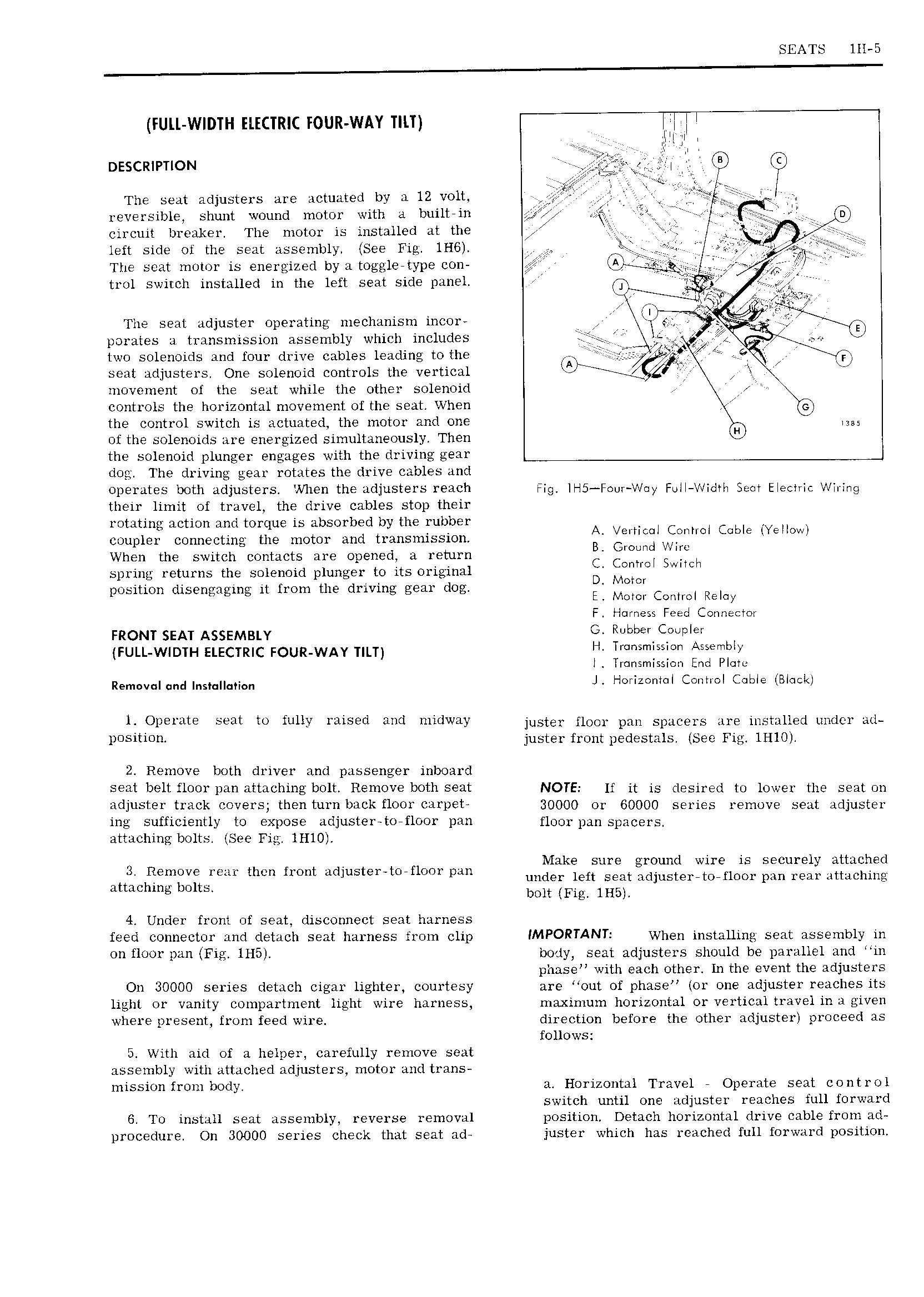
SEATS lll 5 FULL WIDTH ELECTRIC FOUR WAY TILT V l osscmvnow j lg gl t 1 The seat adjusters are actuated by a l2 volt j j Q jr reversible shunt wound motor with a builtrin 0 lZ A J XE circuit breaker The motor is installed at the j T left side of the seat assembly See Fig 1H6 r The scat motor is energized by a toggle type con 1 QV V i trol switch installed in the left seat side panel i VK i ii r The seat adjuster operating mechanism incor V a 0 ij J porates a transmission assembly which includes MQ 4 r L two solenoids and four drive cables leading to the seat adjusters One solenoid controls the vertical l a l i X o movement of the seat while the other solenoid I controls the horizontal movement of the seat When YQ the control switch is actuated the motor and one 2 of the solenoids are energized simultaneously Then ul the solenoid plunger engages with the driving gear dog The driving gear rotates the drive cables and operates both adjusters When the adjusters reach Fig ll I5 FoulV iJ y Foil Width Sem Electric Wiring their limit of travel the drive cables stop their rotating action and torque is absorbed by the rubber V coupler connecting the motor and transmission r i Ei lr l GAME HEHOW When the switch contacts are opened a return r C j gill spring returns the solenoid plunger to its original MCL M w position disengaging it from the driving gear dog E Mmm Control Remy F Hnmess Feed Comiecml mom sem ASSEMBLY G i b e FULL W DTH ELECTRIC FOUR WAY TILT H T l l A b T l Transmission End Plate Remuvnjund ns J l I l i c m l Conhol Cable lBl clo 1 Opertlte Sem to fully Yais d wd midway juster floor pan spacers are installed under ad l 0 iYi juster front pedestals sec lHl0 2 Remove both driver and passenger inboard seat belt floor pan attaching bolt Remove both seat NOTE If it is desired to lower the seat on adjuster track covers then turn back floor carpet 30000 or 60000 series remove seat adjuster ing sufficiently to expose adjuster to floor pan floor pan spacers attaching bolts See Fig lHl0 Make sure ground wire is secureli attached j Remuile FSH then from utllustelxtilrflcior pan under left seat adjuster torfloor pan real attaching attaching bolts bolt Fig lH5 4 Under front of seat disconnect seat harness feed connector and detach seat harness from clip IMPORTANT When installing seat assembly in on floor pan Fig lH5 body seat adjusters should be parallel and in phase with each other In the event the adjusters On 30000 series detach cigar lighter courtesy are out of phase lor one adjuster reaches its light or vanity ooinpartinent light wire harness maximum horizontal or vertical travel in a given where present from feed wire direction before the other adjuster proceed as follows 5 With aid of a helper carefully remove seat assembly with attached adjusters motor and trans mission from body a Horizontal Travel 7 Operate seat control switch until one adjuster reaches full forward 6 To install seat assembly reverse removal position Detach horizontal drive cable from ad procedure On 30000 series check that seat ad juster which has reached full forward position