Jeep Parts Wiki | Ford Parts Wiki
Home | Search | Browse
|
Body Service Manual August 1964 |
|
Prev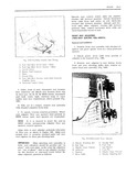
 Next
Next
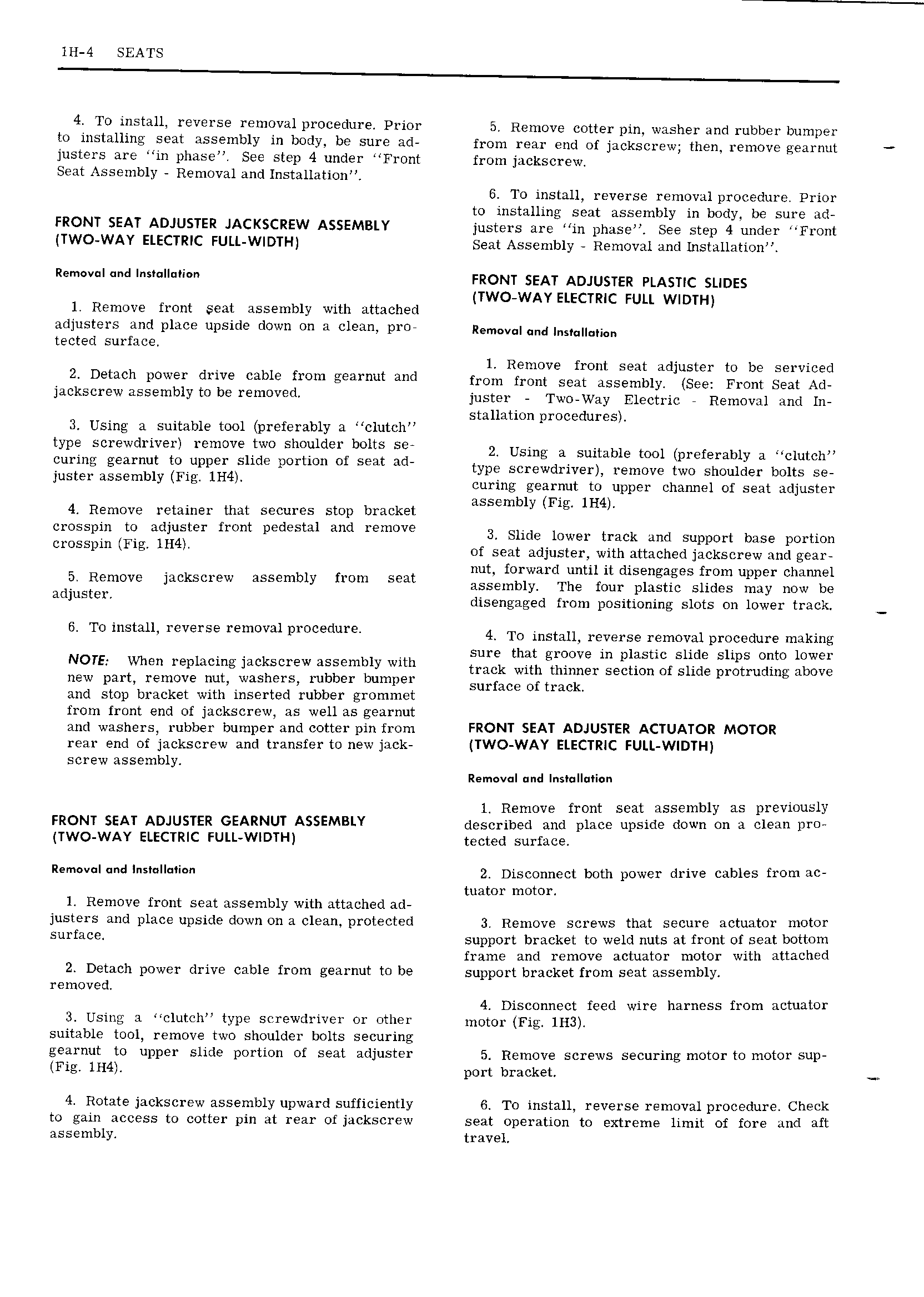
ll I 4 SEATS 4 To install reverse removal procedure Prior 5 Remove cotter pin washer and rubber bumper to installing seat assembly in body be sure ad from rear end of jackscrew then 1 emove gearnut justers are in phase See step 4 under Front from jackscrew Seat Assembly Removal and Installation 6 To install reverse removal procedure Prior to installing seat assembly in body be sure ad FRONT SEAT ADJUSTER JACKSCREW ASSEMBLY justers are in phase See step 4 under Front TWO WAY ELECTRIC FULL WIDTH Seat Assembly Removal and Installation R v I F r RoNT SEAT ADJUSTER PLASTIC suoes TWO WAY ELECTRIC FULL WIDTH 1 Remove front seat assembly with attached adjusters and place upside down on a clean pro Removal and j s j tected surface 1 Remove front seat adjuster to be serviced 2 D t Ch POWGF drive Cable from Efearnut wd from front seat assembly See Front Seat Ad jackScrew SS 1b1yf b r V d juster Two Way Electric A Removal and In stallation procedures 3 Using a suitable tool preferably a clutch type screwdriver remove two shoulder bolts se 24 Using 3 suitable mol prefemblv 3 c1utch wring gearnut to upp I Slide portion Of Seat ad type screwdriver remove two shoulder bolts se Justsr assembly F15 1H4 curing gearnut to upper channel of seat adjuster assembly Fig lH4 4 Remove retainer that secures stop bracket crosspin to adjuster front pedestal and remove 3 Slide lower track and Support base portion Crosspm Fig IH4 of seat adjuster with attached jackscrew and gear nut forward until it disengages from upper chamiel Remove 1 S w assembly from Seat assembly The four plastic slides may now be adjuster disengaged from positioning slots on lower track 6 T0 i Stau reverse removal procedure 4 To install reverse removal procedure making sure that groove in plastic slide slips onto lower NOTE When repmcmg Jackscrew assembly with track with thinner section of slide protruding above new part remove nut washers rubber bumper Surface Oi track and stop bracket with inserted rubber grommet from front end of jackscrew as well as gearnut and washers rubber bumper and cotter pin from FRONT SEAT ADJUSTER ACTUATOR MOTOR rear end of jackscrew and transfer to new jack TWO WAY ELECTRIC FULL WIDTH screw assembly Rem v I und l s II i l Remove front seat assembly as previously FRONT SEAT ADJUSTER GEARNUT ASSEMBLY described and place upside down on a clean pro TWO WAY ELECTRIC FULL WlDTH tgctgd Surface R r v d I S II i 2 Disconnect both power drive cables from ac tuator motor 1 Remove front seat assembly with attached ad justers and place upside down on a clean protected 3 Remove screws that secure actuator motor surface support bracket to weld nuts at front of seat bottom frame and remove actuator motor with attached 2 Detach power drive cable from gearnut to be support bracket from seat assembly removed 4 Disconnect feed wire harness from actuator 3 Using a clutch type screwdriver or other motor Fig H3 suitable tool remove two shoulder bolts securing gearnut to upper slide portion of seat adjuster 5 Remove screws securing motor to motor sup Fig IH4 port bracket Q 4 Rotate jackscrew assembly upward sufficiently 6 To install reverse removal procedure Check to gain access to cotter pin at rear of jackscrew seat operation to extreme limit of fore and aft assembly travel