Jeep Parts Wiki | Ford Parts Wiki
Home | Search | Browse
|
Body Service Manual August 1964 |
|
Prev
 Next
Next
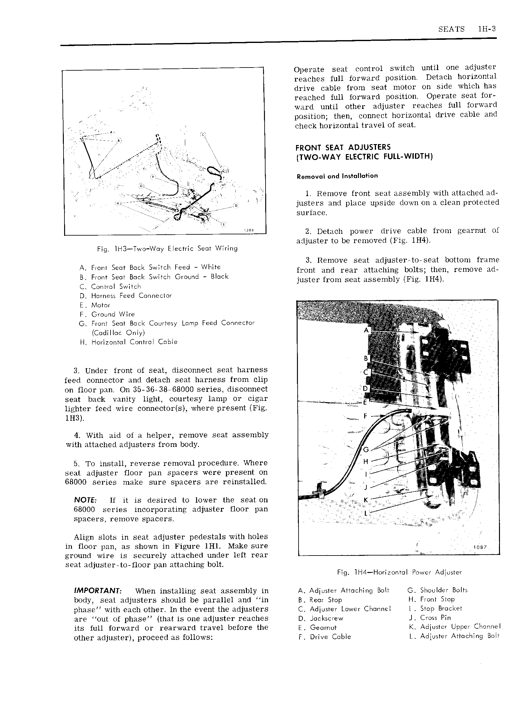
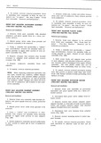
SEATS lll 3 Operate seat control switch until one adjuster reaches full forward position Detacb horizontal drive cable from seat motor on side which has reached full forward position Operate seat for ward until other adjuster reaches full forward position then connect horizontal drive cable and y V check horizontal travel of seat xtzziiff pn j V rtzom sem Amusrzns r Q TWO WAY ELECTRIC FULL WIDTH V r i i Removal and Installation V at ll 79 V 1 Remove front seat assembly with attached ad e Zi r D justers and place uyside down on a clean protected l A surface I 2 Detach nower drive cable from ggearnut of l adjuster to be removed Fig lH4 Fig lH3 Two Way Electric Seot Wiring 5 A S k I V WV 3 Remove seat adjustereto seat bottom frame HON Cm B fl l Fr d L if k front and rear attaching bolts then remove ad Fm Sem BGM Wllcl G n B GC juster from seat assembly Fig IH4 c Control Swiieh D Hornezs Feed Connector E Motor G Front Seat Back Courtesy Lamp Feed Connector r M rz icettattae only H Horizontal Control Cable gj C r rigs il ir 3 Under front of seat disconnect seat harness A feed connector and detach seat harness from clip y tri 7 V V on floor pan On 35 36 38 68000 series disconnect D seat back vanity light courtesy lamp or cigar I lighter feed wire connector s where present Fig 2 J A inst r r v g r 3 4 With aid of a helper remove seat assembly with attached adjusters from body t l l G A V it lh 5 To install reverse removal procedure Where H t if seat adjuster floor pan spacers were present on It r V l 68000 series make sure spacers are reinstalled g J i g NOTE If it is desired to lower the seat on K V j l i 68000 series incorporating adjuster floor pan L yl spacers remove spacers Align slots in seat adjuster pedestals with holes in floor pan as shown in Figure 1Hl Make sure 0 ground wire is securely attached under left rear seat adjuster to floor pan attaching bolt Fig lH4 Hori onto Power Adjuster IMPORTANT When installing seat assembly in A Adjuster Attaching Bolt G Shoulder Bolt body seat adjusters should be parallel and in B Rem Stop H Front Step phase with each other In the event the adjusters CZ Adjuster Lower Channel I Stop Bracket are out of pIiase that is one adjuster reaches D Jockscrew J Cross Pin its full forward or rearward travel before the F Geurnut K Ad ustcr U Jer Cliortnel I PF other adjuster proceed as follows F Drive Cnble L Adjuster Attaching Bolt