Jeep Parts Wiki | Ford Parts Wiki
Home | Search | Browse
|
Body Service Manual August 1964 |
|
Prev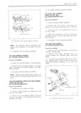
 Next
Next
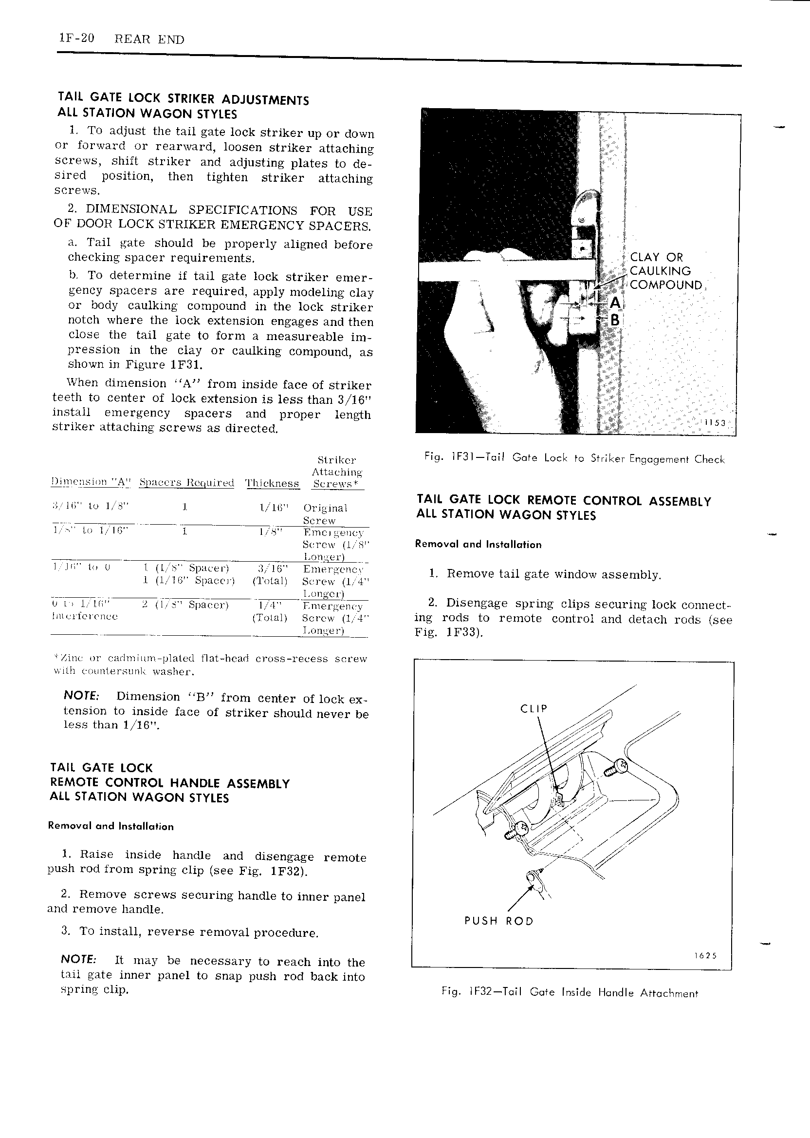
ll 20 REAR END TAIL GATE LOCK STRIKER ADJUSTMENTS ALL STATION WAGON STYLES 1 1 To adjust the tail gate lock striker up or down or forward or rearward loosen striker attaching 2 T screws shift striker and adjusting plates to de I sirecl position then tighten striker attaching g screws 2 DIMENSIONAL SPECIFICATIONS FOR USE E Q OF DOOR LOCK STRIKER EMERGENCY SPACERS V 1 a Tail gate should be properly aligned before I V e 1 CLAY OR checking spacer requirements i CAULKING b To determine if tail gate lock striker emer 7 1 COMpOUND gency spacers are required apply modeling clay K I ppt or body caulking compound in the lock striker x I notch where the lock extension engages and then 3 B close the tail gate to form a measureable im I ax i pression in the clay or caulking compound as I shown in Figure 1F31 i I When dimension A from inside face of striker i I teeth to center of lock extension is less than 3 W16 g install emergency spacers and proper length I 51 striker attaching screws as directed I 1 m Fig iF3l T iI Gate Leek to SriiL ei Engqgemeni Cheek Attaching gi i 1s1 ii Ay s ii 1 s11i i1ii i i 1 iiit I im ss sei ei1 s TAIL GATE LOCK REMOTE CONTROL ASSEMBLY In I i I I I I ALL srAnoN wA oN swiss g Y 1 1 mr 1 1 sr 1i1ni ite n i Screw tl s Removal und Instulluliun e g s1 E I VI I II I II I I II IB EI I 1 Remove tail gate window assembly l Il lni Spatwri Total Screw tl i j j ggaj 21 Disengage spring clips securing lock connect L T in1 sei I it 1 4 ing rods to remote control and detach rods Isee XE Fig 1F33 Ain or r arI1ninn plated t Iat I1c urI r ross recess serew III1 iim IHl SlII I WHSITQI NOTE Dimension B from center of lock ex CLIP tension to inside face of striker should never be I less than 1 IG l z TAIL GATE Locx ll 7 I 1 digg REMOTE CONTROL HANDLE ASSEMBLY ALL STATION WAGON STYLES TIE 7 fQ 1 r s i V A Removul md s ll i n 5 l Raise inside handle and disengage remote ISIrii r T Qiyi push rod from spring clip see Fig 1F32 24 Remove screws securing handle to inner panel and remove handle P Us H RO D 3 To install reverse removal procedure I625 NOTE It may be necessary to reach into the Y tail gate inner panel to snap push rod back into S g 1 p Fig iF32 T iI G e Inside Hrmdle Arraciwmeiv