Jeep Parts Wiki | Ford Parts Wiki
Home | Search | Browse | Marketplace | Messages | FAQ | Guest
|
Body Service Manual August 1964 |
|
Prev

 Next
Next
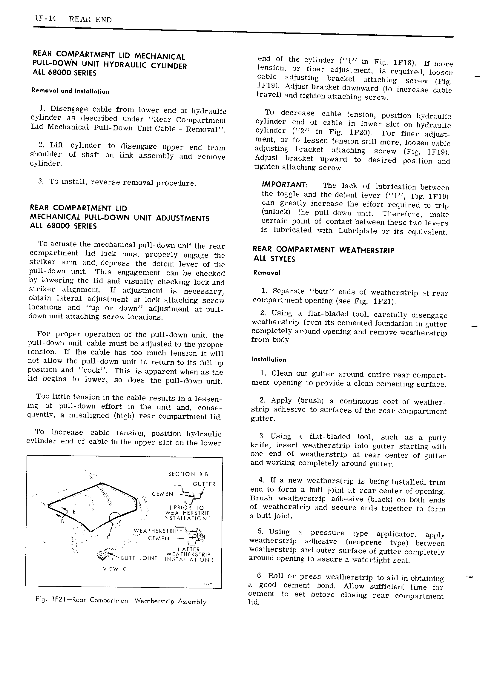
lF 14 REAR END REAR COMPARTMENT LID MECHANICAL end of the cylinder l in Fig lF18 lf more PULL DOWN UNIT HYDRAULIC CYLINDER tension or finer adjustment is required loosen ALL 68000 SERIES cable adjusting bracket attaching screw Fig 1Fl9 Adjust bracket downward to increase cable Removcl nd Ins II i n travel and tighten attaching screw 1 Disengage cable from lower end of hydraulic To decrease cable tension position hydraulic cylinder as described under Rear Compartment cylinder end of cable in lower slot on hydraulic Lid Mechanical Pull Down Unit Cable Removal cylinder 2 in Fig 1F20 For finer adjust ment or to lessen tension still more loosen cable 2 Lift cylinder to disengage upper end from adjusting bracket attaching screw Fig lFl9 shoulder of shaft on link assembly and remove Adjust bracket upward to desired position and cylinder tighten attaching screw 3 To install reverse removal procedure IMPORTANT The lack of lubrication between the toggle and the detent lever l Fig lFl9 can greatly increase the effort required to trip REAR COMPARTMENT LID unlock the pull down unit Therefore make MECHANICAL PULL DOWN UNIT ADJUSTMENTS certain point of contact between these two levers ALL 68000 SERIES is lubricated with Lubriplate or its equivalent To actuate the mechanical pull down unit the rear REAR COMpAR MEN wEA HERg j R p compartment lid lock must properly engage the ALL STYLES striker arm and depress the detent lever of the pull down unit This engagement can be checked R I by lowering the lid and visually checking lock and striker alignment lf adjustment is necessary 1 Separate Ubuttn Ends Of Weatherswill at TEN obtain lateral adjustment at lock attaching sei ew 1 rt t 1 e i e See Fig 1F21 4 locations and up or down adjustment at pull 2 Using 3 f1 1t bl d9dtOOl7 Carefully disengage down unit attaching screw IO 3 ti s weatherstrip from its cemented foundation in gutter completely around opening and remove weatherstrip For proper operation of the pull down unit the from body pull down unit cable must be adjusted to the proper tension lf the cable has too much tension it will lnsmllunw not allow the pull down unit to return to its full up position and cock This is apparent when as the 1 Clean out gutter around entire rear compart lid begins to lower so does the pull down unit ment opening to provide a clean cementing surface Too little tension in the cable results in a lessen 2 Apply brush a continuous coat of weather ing of pull down effort in the unit and conse strip adhesive to surfaces of the rear compartment quently a misaligned high rear compartment lid gutter To increase cable tension position hydraulic 3 Using a flat bladed tool such as a putty cylinder end Of cable in the upp rS1 t on the lewer knife insert weatherstrip into gutter starting with one end of weatherstrip at rear center of gutter and working completely around gutter Y SECIION M 4 If a new weatherstrip is being installed trim ouvre end to form a butt joint at rear center of opening CEMENT Brush weatherstrip adhesive black on both ends l r PRIESI TO of weatherstrip and secure ends together to form B imiilititt wi 1 i i V WEATHERSTRIF5 L 5 Using a pressure type applicator apply L c V CEMENT weatherstrip adhesive neoprene type between 7 I 0 AFTER weatherstrip and outer surface of gtter completely BUTT 0 4 fj around opening to assure a watertight seal VIEW C 6 Roll or press weatherstrip to aid in obtaining a good cement bond Allow sufficient time for cement to set before closing rear compartment Fig IF2I Re r Compartment Weothersrrip Assembly lid

 Next
Next