Jeep Parts Wiki | Ford Parts Wiki
Home | Search | Browse
Prev
 Next
Next
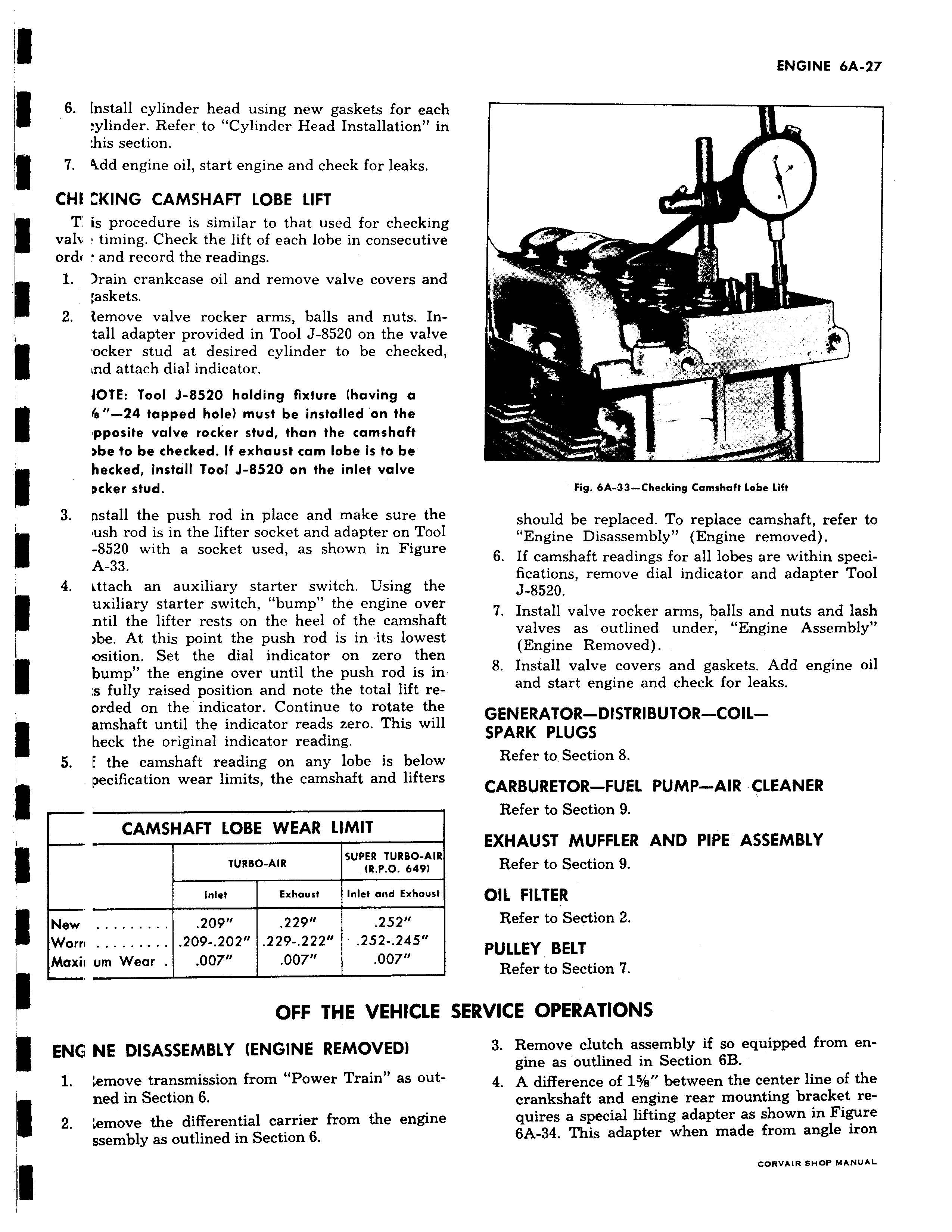
6 fnstall cylinder head using new gaskets for each ylinder Refer to Cylinder Head Installation in his section 7 Add engine oil start engine and check for leaks CHF W KING CAMSHAFT LOBE LIFT T is procedure is similar to that used for checking valv timing Check the lift of each lobe in consecutive ordc v and record the readings 1 Irain crankcase oil and remove valve covers and askets 2 i emove valve rocker arms balls and nuts Intall adapter provided in Tool J 8520 on the valve ocker stud at desired cylinder to be checked ind attach dial indicator JOTE Tool J 8520 holding fixture having a r 6 24 tapped hole must be installed on the ipposite valve rocker stud than the camshaft Dbe to be checked If exhaust cam lobe is to be hecked install Tool J 8520 on the inlet valve Dcker stud 3 nstall the push rod in place and make sure the ush rod is in the lifter socket and adapter on Tool 8520 with a socket used as shown in Figure A 33 4 Lttach an auxiliary starter switch Using the uxiliary starter switch bump the engine over ntil the lifter rests on the heel of the camshaft be At this point the push rod is in its lowest osition Set the dial indicator on zero then bump the engine over until the push rod is in a fully raised position and note the total lift reorded on the indicator Continue to rotate the amshaft until the indicator reads zero This will heck the original indicator reading 5 E the camshaft reading on any lobe is below pecification wear limits the camshaft and lifters CAMSHAFT LOBE WEAR LIMIT AIR SUPER TURBO AIR TURBO AIR 6491 Inlet Exhaust Inlet and Exhaust New 209 229 252 Worn 209 202 229 222 252 245 Maxii um Wear 007 007 007 OFF THE VEHICLE ENG NE DISASSEMBLY ENGINE REMOVED 1 Lemove transmission from Power Train as outned in Section 6 2 emove the differential carrier from the engine ssembly as outlined in Section 6 Fig 6A 33 Checking Camshaft Lobe Lift should be replaced To replace camshaft refer to Engine Disassembly Engine removed ns remove dial indicator and adapter Tool J 8520 7 Install valve rocker arms balls and nuts and lash valves as outlined under Engine Assembly Removed 8 Install valve covers and gaskets Add engine oil and start engine and check for leaks Refer to Section 8 Refer to Section 9 Refer to Section 9 Refer to Section 2 Refer to Section 7 ERVICE OPERATIONS SPARK PLUGS CARBURETOR FUEL PUMP AIR CLEANER EXHAUST MUFFLER AND PIPE ASSEMBLY OIL FILTER PULLEY BELT equipped gine as outlined in Section 6B difference 4 A engine mounting uires a special lifting adapter as shown in Figure