Jeep Parts Wiki | Ford Parts Wiki
Home | Search | Browse
Prev

 Next
Next
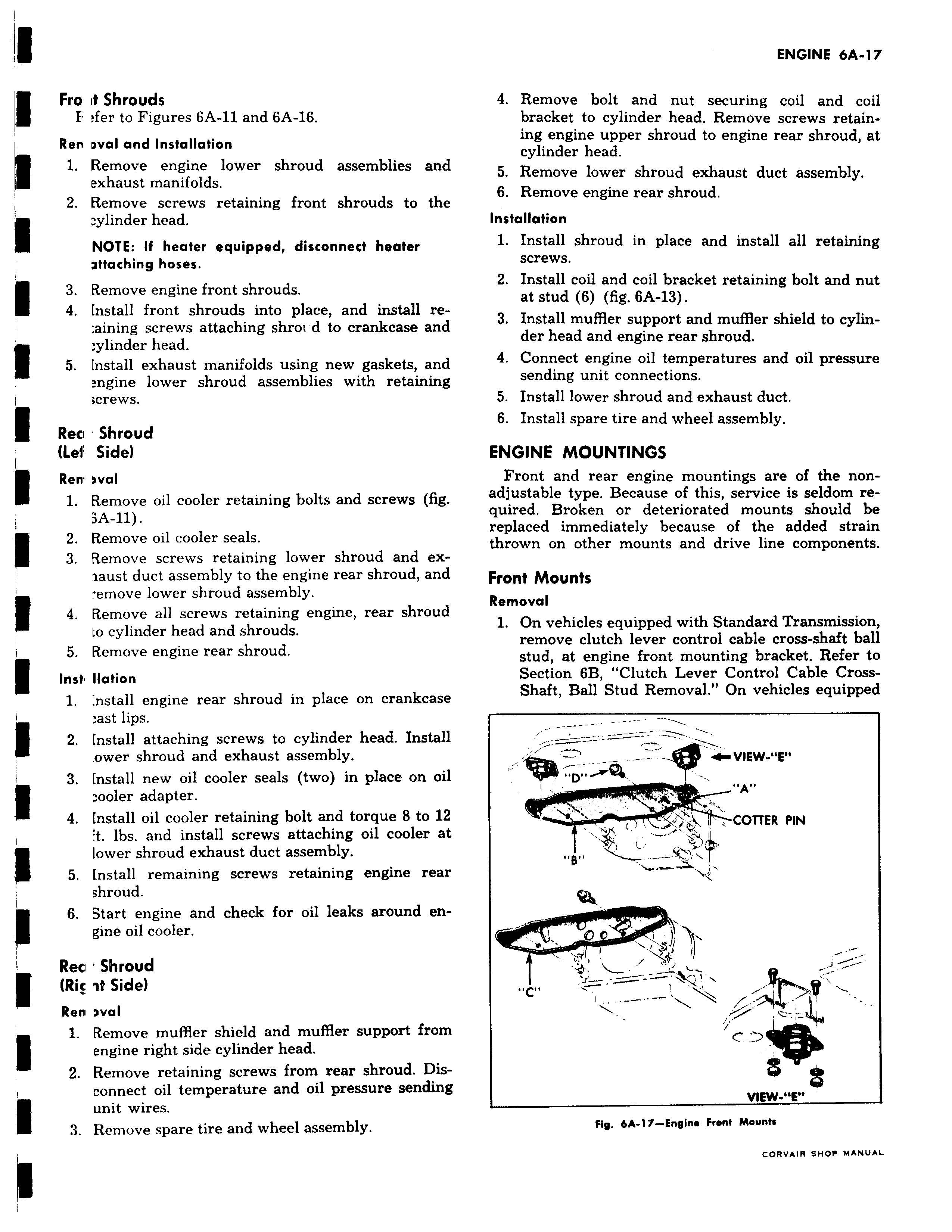
Fro it Shrouds 11 fer to Figures 6A 11 and 6A 16 Rer wal and Installation 1 Remove engine lower shroud assemblies and exhaust manifolds 2 Remove screws retaining front shrouds to the ylinder head NOTE If heater equipped disconnect heater pttaching hoses 3 Remove engine front shrouds 4 Install front shrouds into place and install re aining screws attaching shroad to crankcase and ylinder head LLL 5 fnstall exhaust manifolds using new gaskets and engine lower shroud assemblies with retaining crews Rec Shroud Lef Side Ren wal l Remove oil cooler retaining bolts and screws fig 3A 11 2 Remove oil cooler seals 3 Remove screws retaining lower shroud and exlaust duct assembly to the engine rear shroud and emove lower shroud assembly 4 Remove all screws retaining engine rear shroud to cylinder head and shrouds 5 Remove engine rear shroud Inst Ilation 1 nstall engine rear shroud in place on crankcase ast lips 2 Install attaching screws to cylinder head Install ower shroud and exhaust assembly 3 Install new oil cooler seals two in place on oil I ooler adapter 4 Install oil cooler retaining bolt and torque 8 to 12 t lbs and install screws attaching oil cooler at lower shroud exhaust duct assembly 5 nstall remaining screws retaining engine rear shroud I 6 Start engine and check for oil leaks around engine oil cooler Rea Shroud I Ric it Side Rern oval 1 Remove muffler shield and muffler support from engine right side cylinder head 2 Remove retaining screws from rear shroud Disconnect oil temperature and oil pressure sending unit wires 3 Remove spare tire and wheel assembly 4 Remove bolt and nut securing coil and coil bracket to cylinder head Remove screws retaining engine upper shroud to engine rear shroud at cylinder head 5 Remove lower shroud exhaust duct assembly 6 Remove engine rear shroud Installation 1 Install shroud in place and install all retaining screws 2 Install coil and coil bracket retaining bolt and nut at stud 6 fig 6A 13 3 Install muffler support and muffler shield to cylinder head and engine rear shroud 4 Connect engine oil temperatures and oil pressure sending unit connections 5 Install lower shroud and exhaust duct 6 Install spare tire and wheel assembly ENGINE MOUNTINGS Front and rear engine mountings are of the nonadjustable type Because of this service is seldom required Broken or deteriorated mounts should be replaced immediately because of the added strain thrown on other mounts and drive line components Front Mounts Removal 1 On vehicles equipped with Standard Transmission remove clutch lever control cable cross shaft ball stud at engine front mounting bracket Refer to Section 6B Clutch Lever Control Cable CrossShaft Ball Stud Removal On vehicles equipped l 4 VIEW Ell p W COTTER PIN W i e VIEW E Fly 6A 17 Engine Front Mounts CORVAIR SHOP MANUAL

 Next
Next