Jeep Parts Wiki | Ford Parts Wiki
Home | Search | Browse | Marketplace | Messages | FAQ | Guest
Prev
 Next
Next
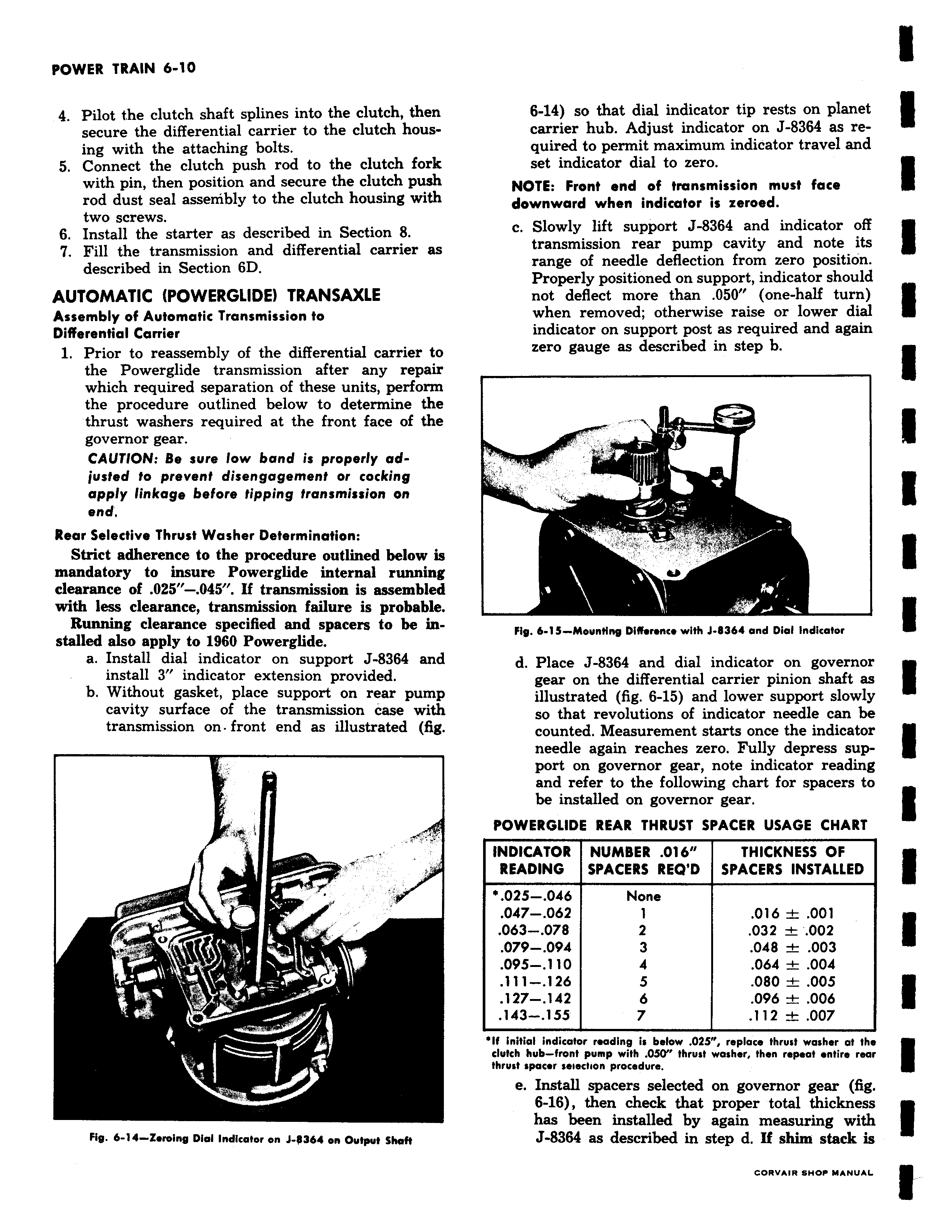
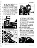
r vvtcn Wnu v v 4 Pilot the clutch shaft splines into the clutch then secure the differential carrier to the clutch housing with the attaching bolts 5 Connect the clutch push rod to the clutch fork with pin then position and secure the clutch push rod dust seal assembly to the clutch housing with two screws 6 Install the starter as described in Section 8 7 Fill the transmission and differential carrier as described in Section 6D AUTOMATIC POWERGLIDE TRANSAXLE Assembly of Automatic Transmission to Differential Carrier 1 Prior to reassembly of the differential carrier to the Powerglide transmission after any repair which required separation of these units perform the procedure outlined below to determine the thrust washers required at the front face of the governor gear CAUTION Be sure low band is properly adjusted to prevent disengagement or cocking apply linkage before tipping transmission on end Rear Selective Thrust Washer Determination Strict adherence to the procedure outlined below is mandatory to insure Powerglide internal running clearance of 025 045 If transmission is assembled with less clearance transmission failure is probable Running clearance specified and spacers to be installed also apply to 1960 Powerglide a Install dial indicator on support J 8364 and install 3 indicator extension provided b Without gasket place support on rear pump cavity surface of the transmission case with transmission on front end as illustrated fig U w Fig 6 14 Zeroing Dial Indicator on J 0364 on Output Shaft 6 14 so that dial indicator tip rests on planet carrier hub Adjust indicator on J 8364 as required to permit maximum indicator travel and set indicator dial to zero NOTE Front end of transmission must face downward when indicator is zeroed c Slowly lift support J 8364 and indicator off transmission rear pump cavity and note its range of needle deflection from zero position Properly positioned on support indicator should not deflect more than 050 one half turn when removed otherwise raise or lower dial indicator on support post as required and again zero gauge as described in step b rr r 7 Er Fig 6 1 5 Mounting Difference with J 9364 and Dial Indicator d Place J 8364 and dial indicator on governor gear on the differential carrier pinion shaft as illustrated fig 6 15 and lower support slowly so that revolutions of indicator needle can be counted Measurement starts once the indicator needle again reaches zero Fully depress support on governor gear note indicator reading and refer to the following chart for spacers to be installed on governor gear POWERGLIDE REAR THRUST SPACER USAGE CHART INDICATOR NUMBER 016 THICKNESS OF READING SPACERS REQ D SPACERS INSTALLED 025 046 None 047 062 1 016 001 063 078 2 032 002 079 094 3 048 003 095 110 4 064 004 111 126 5 080 005 127 142 6 096 006 143 155 7 112 007 If initial indicator reading is below 025 replace thrust washer at the clutch hub front pump with OSO thrust washer then repeat entire rear thrust spacer seiectlon procedure e Install spacers selected on governor gear fig 6 16 then check that proper total thickness has been installed by again measuring with J 8364 as described in step d If shim stack is