Jeep Parts Wiki | Ford Parts Wiki
Home | Search | Browse
Prev
 Next
Next
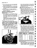
Ii the Corvair Powerglide selective thrust wash ers ire used at two locations fig 6E 1 1 At the front of the transmission between the front ump body and the clutch drum 2 At the rear of the transmission between the rear ace of the planet carrier hub transmission outPut member and the front face of the governor fear F DM the serviceman s standpoint the use of selective thrust washers at both the front and rear is a dist ict advantage as final transmission end play ad just ient can be made from either end of the transmission whichever is most advantageous Also there is I no n ondition in which the selective washers would be gap ed for both locations F r example assume that a new ring gear and pinion is tr be installed in the differential carrier but no work is ci ine on the transmission This requires that the diffe ential carrier be separated from the transmission Afte completing the repair the serviceman would perl rm the thrust washer selection procedure at the rear with J 8364 and a dial indicator install the requir d washers on the governor gear and then reassem le the transmission and axle r A a second example assume that the Powerglide higl clutch fails but no rear axle repair is required In this case the repair should be performed with the trart mission left assembled to the axle and engine it is n t necessary to remove the power train from the lifti g fixture used to remove the unit from the vehicle Onc the repair was completed thrust washer selection would be made prior to installation of the front pun at the clutch drum front with J 8371 the thru t washer selected installed and then the remaining ssembly operations completed Ir the third and final case assume that repairs are reqt red in both the transmission and axle This requir s separation of the axle from the transmission Reb ild of the axle would be exactly as described in ASSEMBLY OF POWER TF THA E OR FOUR SPEED TRANSAXLE Asso nbly of Three or Four Speed Transmission and Diffo ential Carrier 1 kpply a new gasket fig 6 9 to either the mountng face of the transmission or carrier with petroeum jelly 2 ouple the transmission to the carrier being sure o engage the splines of the transmission mainhaft to the internal splines of the pinion in the lifferential carrier 3 ecure the transmission to the carrier with four iolts two on the right are driven from the trans fff nission side and the two left bolts are driven from he carrier side Torque bolts to 24 32 ft lbs Section 6C and Powerglide overhaul would be exactly as described in Section 6E with the exception that the thrust washer would be installed at the front clutch drum front pump location during assembly without performing any selection procedure Once both the axle and transmission are fully assembled selection of final end play washers would be made at the rear governor gear and assembly of the Powerglide to the differential carrier could be completed Analyzing the three cases the serviceman can summarize the thrust washer selection requirements in one phrase If the repair requires axle and transmission separation make the selection at the rear Obviously if they are not separated the rear thrust washer is inaccessible and the selection must be made at the front To the serviceman experienced with conventional automatic transmissions the use of a selective washer at the front is common and easily understood but the why of the rear selective thrust washer is not readily apparent The reason for the rear selective thrust washer is more easily understood by considering the proximity of the components involved and the designs embodied in the integration of the transmission and differential carrier rear axle Observing the sectional view fig 6E 1 it will be noted that the transmission governor gear mounts on the pinion gear shaft the position of which is controlled by pinion bearings in the differential carrier and the machining of the pinion shaft and the differential carrier bearing bores The differential pinion shaft couples with the hub of the transmission planet gearset and thus creates the vehicle output shaft Relative to the transmission the governor gear front face is the first solid forward driveline point available to absorb transmission thrust and useable as a locating line for transmission internal components Selective fit washers are used at this point to compensate for differential carrier and transmission tolerances to permit unit interchangeability AIN MAJOR COMPONENTS Assembly of Three or Four Speed Transaxie to the Engine 1 Install the clutch release bearings and clutch fork fig 6 8 on the differential carrier The bearing slips over the shaft and the fork has a spring retainer and socket which attaches to a ball stud on the carrier 2 Install the clutch shaft in the Transaxle then check the distance from the end of the clutch release bearing shaft to the end of the clutch shaft If fully engaged the dimension should be 2 i 16 3 Support the Transaxle with a chain falls or other suitable lift and an improvised sling then align the attaching bolt holes in the differential carrier and clutch housing