Jeep Parts Wiki | Ford Parts Wiki
Home | Search | Browse | Marketplace | Messages | FAQ | Guest
Prev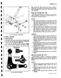
 Next
Next
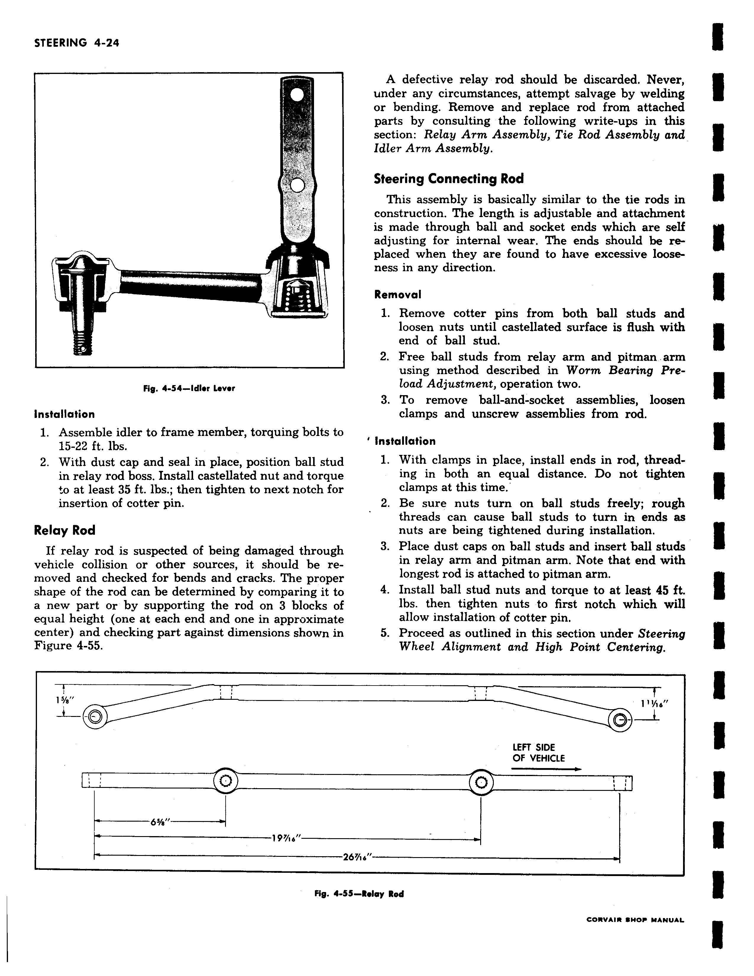
s 3 F wait Fig 4 54 Idler Lever Installation 1 Assemble idler to frame member torquing bolts to 15 22 ft lbs 2 With dust cap and seal in place position ball stud in relay rod boss Install castellated nut and torque o at least 35 ft lbs then tighten to next notch for insertion of cotter pin Relay Rod If relay rod is suspected of being damaged through vehicle collision or other sources it should be removed and checked for bends and cracks The proper shape of the rod can be determined by comparing it to a new part or by supporting the rod on 3 blocks of equal height one at each end and one in approximate center and checking part against dimensions shown in Figure 4 55 15 8 19 ie I Zb Fig 4 SS A defective relay rod should be discarded Never under any circumstances attempt salvage by welding or bending Remove and replace rod from attached parts by consulting the following write ups in this section Relay Arm Assembly Tie Rod Assembly and Idler Arm Assembly Steering Connecting Rod This assembly is basically similar to the tie rods in construction The length is adjustable and attachment is made through ball and socket ends which are self adjusting for internal wear The ends should be replaced when they are found to have excessive looseness in any direction Removal 1 Remove cotter pins from both ball studs and loosen nuts until castellated surface is flush with end of ball stud 2 Free ball studs from relay arm and pitman arm using method described in Worm Bearing Preload Adjustment operation two 3 To remove ball and socket assemblies loosen clamps and unscrew assemblies from rod Installation 1 With clamps in place install ends in rod threading in both an equal distance Do not tighten clamps at this time 2 Be sure nuts turn on ball studs freely rough threads can cause ball studs to turn in ends as nuts are being tightened during installation 3 Place dust caps on ball studs and insert ball studs in relay arm and pitman arm Note that end with longest rod is attached to pitman arm 4 Install ball stud nuts and torque to at least 45 ft lbs then tighten nuts to first notch which will allow installation of cotter pin 5 Proceed as outlined in this section under Steering Wheel Alignment and High Point Centering LEFT SIDE OF VEHICLE I6 Relay Rod