Jeep Parts Wiki | Ford Parts Wiki
Home | Search | Browse
Prev
 Next
Next
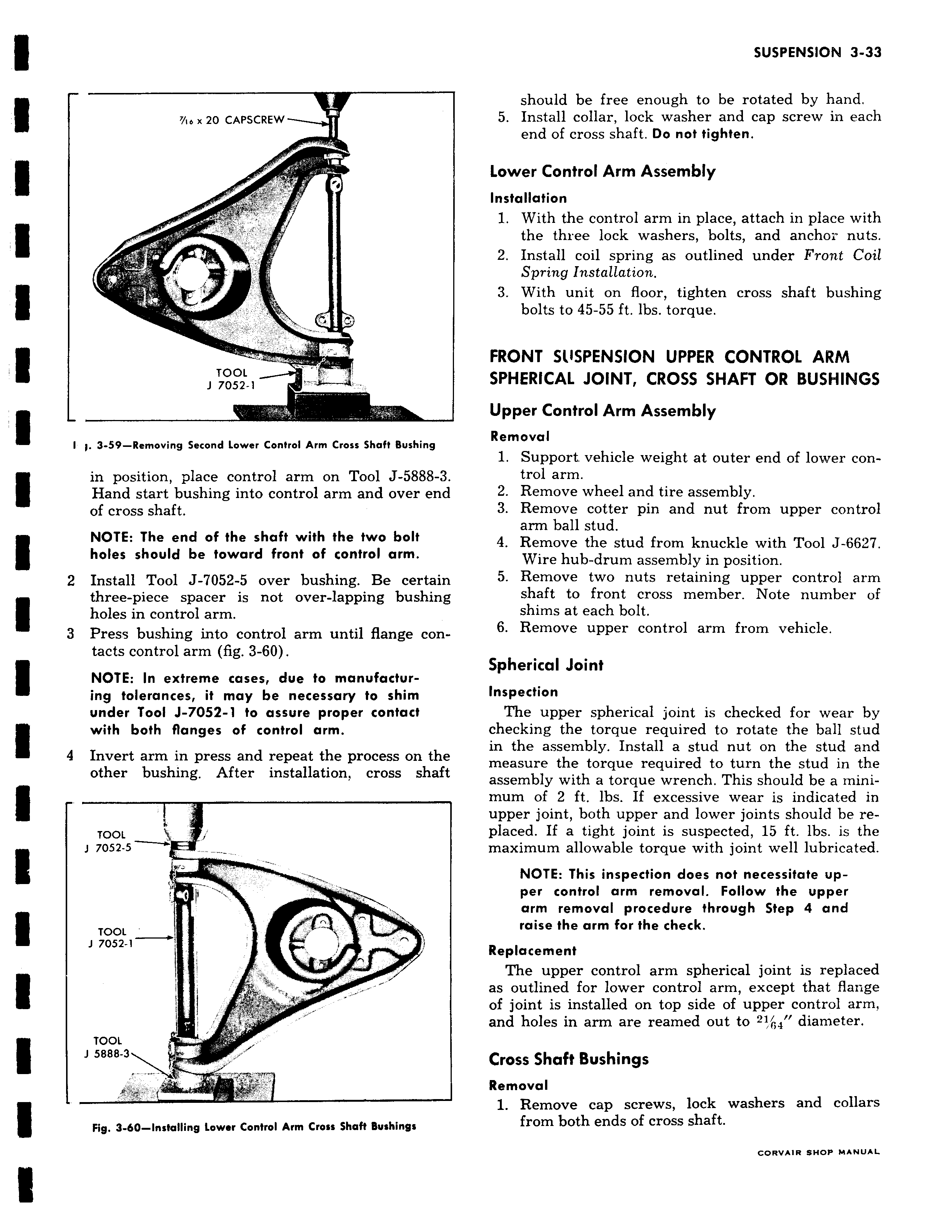
YI e x 20 CAPSCREW D I f4 4 I TOOL J 7osz i u I i 3 59 Removing Second Lower Control Arm Cross Shaft Bushing in position place control arm on Tool J 5888 3 Hand start bushing into control arm and over end of cross shaft NOTE The end of the shaft with the two bolt holes should be toward front of control arm 2 Install Tool J 7052 5 over bushing Be certain three piece spacer is not over lapping bushing holes in control arm 3 Press bushing into control arm until flange contacts control arm fig 3 60 NOTE In extreme cases due to manufacturing tolerances it may be necessary to shim under Tool J 7052 1 to assure proper contact with both flanges of control arm 9 Invert arm in press and repeat the process on the other bushing After installation cross shaft TOOL J 7052 s TOOL 1 7052 1 I TOOL J 5888 3 s Fig 3 60 Installing Lower Control Arm Cross Shaft Bushings should be free enough to be rotated by hand 5 Install collar lock washer and cap screw in each end of cross shaft Do not tighten Lower Control Arm Assembly Installation 1 With the control arm in place attach in place with the three lock washers bolts and anchor nuts 2 Install coil spring as outlined under Front Coil Spring Installation 3 With unit on floor tighten cross shaft bushing bolts to 45 55 ft lbs torque FRONT SUSPENSION UPPER CONTROL ARM SPHERICAL JOINT CROSS SHAFT OR BUSHINGS Upper Control Arm Assembly Removal 1 Support vehicle weight at outer end of lower control arm 2 Remove wheel and tire assembly 3 Remove cotter pin and nut from upper control arm ball stud 4 Remove the stud from knuckle with Tool J 6627 Wire hub drum assembly in position 5 Remove two nuts retaining upper control arm shaft to front cross member Note number of shims at each bolt 6 Remove upper control arm from vehicle Spherical Joint Inspection The upper spherical joint is checked for wear by checking the torque required to rotate the ball stud in the assembly Install a stud nut on the stud and measure the torque required to turn the stud in the assembly with a torque wrench This should be a minimum of 2 ft lbs If excessive wear is indicated in upper joint both upper and lower joints should be replaced If a tight joint is suspected 15 ft lbs is the maximum allowable torque with joint well lubricated NOTE This inspection does not necessitate up per control arm removal Follow the upper arm removal procedure through Step 4 and raise the arm for the check Replacement The upper control arm spherical joint is replaced as outlined for lower control arm except that flange of joint is installed on top side of upper control arm and holes in arm are reamed out to 2 diameter Cross Shaft Bushings Removal 1 Remove cap screws lock washers and collars from both ends of cross shaft CORVAIR SHOP MANUAL