Jeep Parts Wiki | Ford Parts Wiki
Home | Search | Browse
Prev

 Next
Next
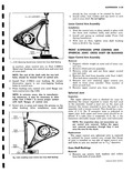
f r W A r I 9I e 31 00 N11 7 Fig 3 57 Freeing Ball Stud Coil Spring Installation 1 Seat spring in tower with end of spring coil in contact with step in spring seat 2 Swing lower arm up as far as possible and seat spring in control arm as above 3 Place jack or screwstand under lower control arm and raise until ball stud may be placed into knuckle boss hole be sure dust cap is in posi tion on ball stud Check position of spring in both seats from time to time while raising arm 4 When stud will enter hole lower jack and install ball stud nut and torque 60 94 ft lbs align castellation in nut with hole in ball stud and install cotter pin 5 Lower vehicle to floor or raise lower control arm far enough to position upper rebound bumper over its hole Lubricate point of bumper with Ru Glide or Door Ease and place point in hole Slowly raise car from floor or lower the lower control arm until upper arm presses point of bumper through the hole in the spring tower SPHERICAL JOINTS Removal Remove coil spring as explained in the foregoing outline and continue as follows 1 With control arm hanging free but still attached to crossmember remove grease fitting and nut from upper side of lower control arm 2 Mark center of rivet heads with center punch and drill through heads with 1 4 drill 3 Cut off rivet heads with cold chisel and remove balance of rivetes with punch Remove spherical joint assembly Installation 1 Position new assembly on control arm and install special bolts through mounting holes Install nuts on bolts and spherical joint mounting stud NOTE Do not substitute any bolts for those specified for use in the replacement of spherical joints 2 Place dust cover over ball stud and assemble suspension as outlined under Front Coil SpringInstallation Cross Shaft and or Bushings Removal 1 Remove bolt lockwasher and collar from each end of cross shaft 2 Thread a 7 16 x20 capscrew furnished with Tool J 5888 to the bottom of the threads in one end of the cross shaft 3 Support control arm in an arbor press on Tool J 5888 3 as shown in Figure 3 58 NOTE Be certain bushing flange does not contact support 1ax20 CAPSCREW a I O r r 0 TOOL J 5888 3 TOOL J 7oss i Fig 3 58 Removing Lower Control Arm Cross Shaft Bushing 4 Press on cap screw until bushing is free of control arm Discard bushing 5 Remove cap screw from cross shaft Insert it in other end of shaft Invert control arm on support fig 3 59 Again be certain bushing flange does not contact support 6 Press on cap screw until bushing is free of control arm Discard bushing Installation 1 With cross shaft in control arm and Tool J 7052 1 eowvuw aweV uAuum