Jeep Parts Wiki | Ford Parts Wiki
Home | Search | Browse
Prev

 Next
Next
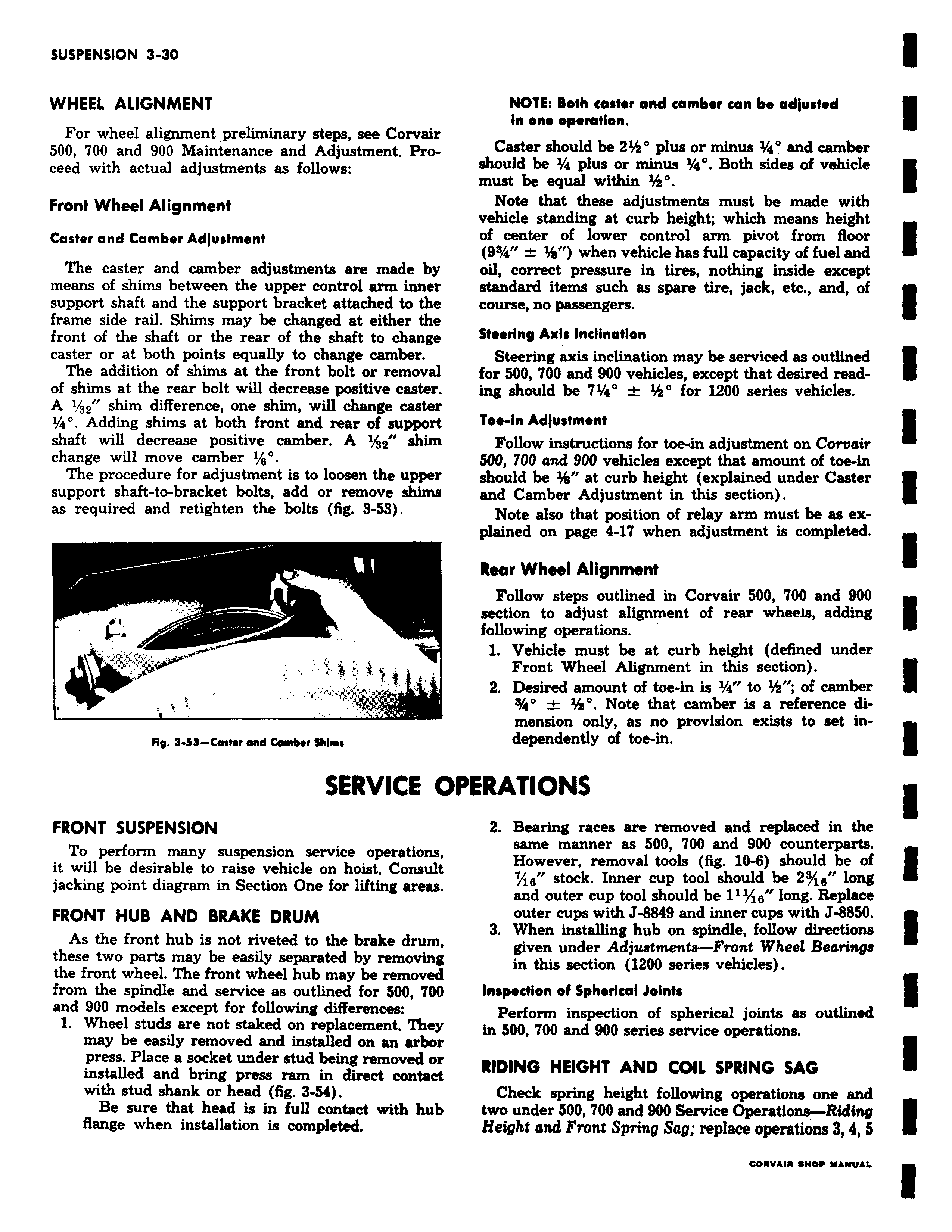
WHEEL ALIGNMENT For wheel alignment preliminary steps see Corvair 500 700 and 900 Maintenance and Adjustment Proceed with actual adjustments as follows Front Wheel Alignment Caster and Camber Adjustment The caster and camber adjustments are made by means of shims between the upper control arm inner support shaft and the support bracket attached to the frame side rail Shims may be changed at either the front of the shaft or the rear of the shaft to change caster or at both points equally to change camber The addition of shims at the front bolt or removal of shims at the rear bolt will decrease positive caster A 1 32 shim difference one shim will change caster a Adding shims at both front and rear of support shaft will decrease positive camber A 1 32 shim change will move camber 1 e The procedure for adjustment is to loosen the upper support shaft to bracket bolts add or remove shims as required and retighten the bolts fig 3 53 Rip 3 53 Caster and mb r Shims SERVICE O FRONT SUSPENSION To perform many suspension service operations it will be desirable to raise vehicle on hoist Consult jacking point diagram in Section One for lifting areas FRONT HUB AND BRAKE DRUM As the front hub is not riveted to the brake drum these two parts may be easily separated by removing the front wheel The front wheel hub may be removed from the spindle and service as outlined for 500 700 and 900 models except for following differences 1 Wheel studs are not staked on replacement They may be easily removed and installed on an arbor press Place a socket under stud being removed or installed and bring press ram in direct contact with stud shank or head fig 3 54 Be sure that head is in full contact with hub flange when installation is completed NOTE Both caster and camber can be adjusted in one operation Caster should be 2 plus or minus 1 a and camber should be t a plus or minus 1 a Both sides of vehicle must be equal within Note that these adjustments must be made with vehicle standing at curb height which means height of center of lower control arm pivot from floor 93 a when vehicle has full capacity of fuel and oil correct pressure in tires nothing inside except standard items such as spare tire jack etc and of course no passengers Steering Axis Inclination Steering axis inclination may be serviced as outlined for 500 700 and 900 vehicles except that desired reading should be 71 4 for 1200 series vehicles Tee in Adjustment Follow instructions for toe4n adjustment on Corvair 500 700 and 900 vehicles except that amount of toe in should be at curb height explained under Caster and Camber Adjustment in this section Note also that position of relay arm must be as explained on page 4 17 when adjustment is completed Rear Wheel Alignment Follow steps outlined in Corvair 500 00 and 900 section to adjust alignment of rear wheels adding following operations 1 Vehicle must be at curb height defined under Front Wheel Alignment in this section 2 Desired amount of toe in is 2 a to of camber s a Note that camber is a reference dimension only as no provision exists to set independently of toe in PERATIONS 2 Bearing races are removed and replaced in the same manner as 500 700 and 900 counterparts However removal tools fig 10 6 should be of 6 stock Inner cup tool should be 23 ls long and outer cup tool should be 111 18 long Replace outer cups with J 8849 and inner cups with J 8850 3 When installing hub on spindle follow directions given under Adjustments Front Wheel Bearings in this section 1200 series vehicles Inspection of Spherical Joints Perform inspection of spherical joints as outlined in 500 700 and 900 series service operations RIDING HEIGHT AND COIL SPRING SAG Check spring height following operations one and two under 500 700 and 900 Service Operations Riding Height and Front Spring Sag replace operations 3 4 5

 Next
Next