Jeep Parts Wiki | Ford Parts Wiki
Home | Search | Browse
Prev

 Next
Next
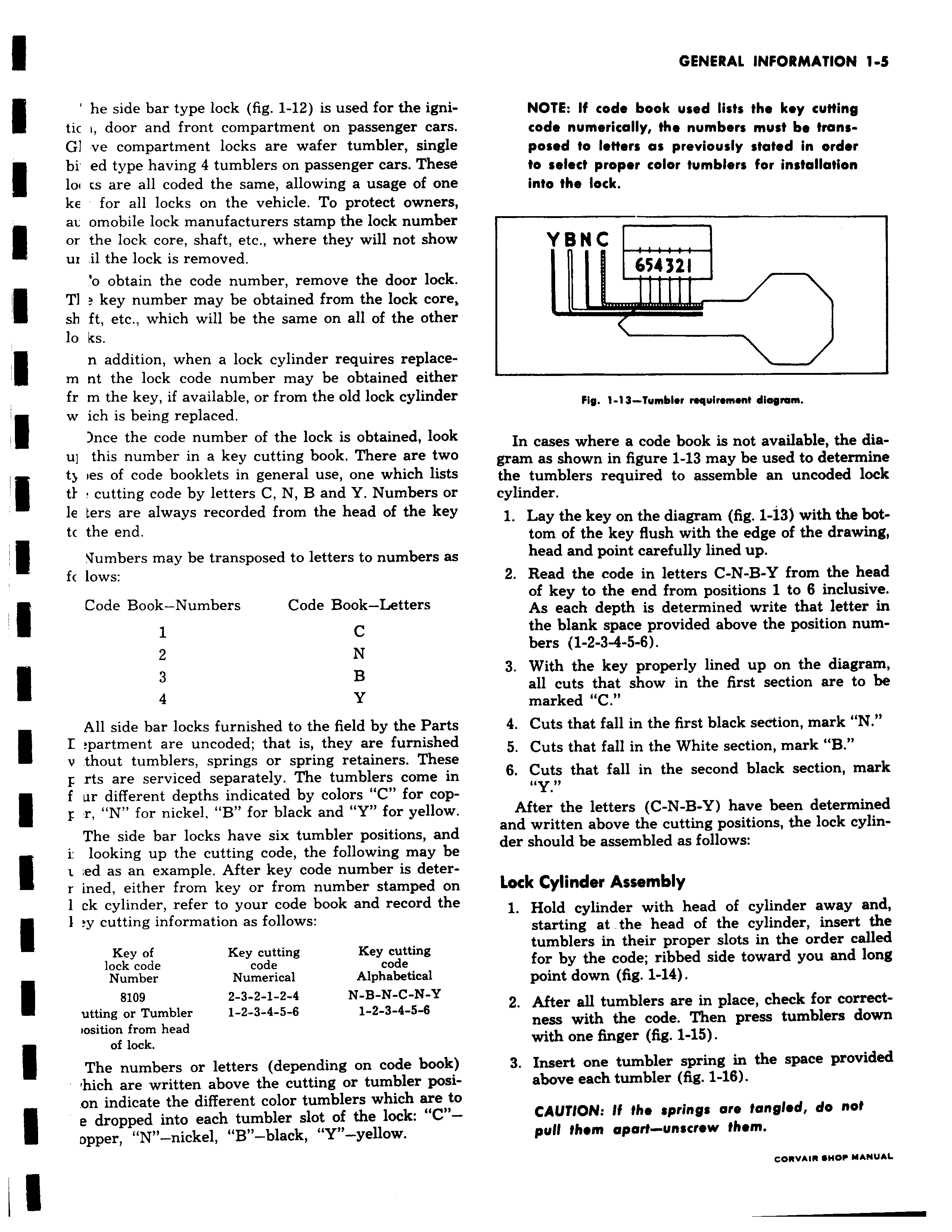
he side bar type lock fig 1 12 is used for the igni tic i door and front compartment on passenger car GI ve compartment locks are wafer tumbler sing bi ed type having 4 tumblers on passenger cars Thes loi is are all coded the same allowing a usage of on ke for all locks on the vehicle To protect owner au omobile lock manufacturers stamp the lock numbe or the lock core shaft etc where they will not shov m il the lock is removed o obtain the code number remove the door loch TI key number may be obtained from the lock core sh ft etc which will be the same on all of the othe lo ks n addition when a lock cylinder requires replace m nt the lock code number may be obtained eithe fr m the key if available or from the old lock cylinde w ich is being replaced nce the code number of the lock is obtained lool u this number in a key cutting book There are twi e ty ies of code booklets in general use one which list ti cutting code by letters C N B and Y Numbers o le ters are always recorded from the head of the ke tc the end Slumbers may be transposed to letters to numbers a ft lows Code Book Numbers Code Book Letters 1 C 2 N 3 B 4 Y All side bar locks furnished to the field by the Part I partment are uncoded that is they are furnishec v thout tumblers springs or spring retainers Thesi F rts are serviced separately The tumblers come ii f ur different depths indicated by colors C for cop r N for nickel B for black and Y for yellow The side bar locks have six tumbler positions an e i looking up the cutting code the following may bo t ed as an example After key code number is deter r ined either from key or from number stamped oi 1 ck cylinder refer to your code book and record thi 1 y cutting information as follows Key of Key cutting Key cutting lock code code code Number Numerical Alphabetical 8109 2 3 2 1 2 4 N B N C N Y utting or Tumbler 1 2 3 4 5 6 1 2 3 4 5 6 iosition from head of lock The numbers or letters depending on code book hich are written above the cutting or tumbler posi on indicate the different color tumblers which are ti e dropped into each tumbler slot of the lock C Dpper N nickel B black Y11 yellow NOTE If code book used lists the key cutting code numerically the numbers must be trans e posed to letters as previously stated in order to select proper color tumblers for installation e into the lock r YBNC 654 321 c r r Fig 1 13 Tumblsr nequinmant diagram In cases where a code book is not available the diagram as shown in figure 1 13 may be used to determine the tumblers required to assemble an uncoded lock cylinder 1 Lay the key on the diagram fig 1 13 with the bottom of the key flush with the edge of the drawing head and point carefully lined up 2 Read the code in letters C N B Y from the head of key to the end from positions 1 to 6 inclusive As each depth is determined write that letter in the blank space provided above the position numbers 1 2 3 4 5 6 3 With the key properly lined up on the diagram all cuts that show in the first section are to be marked C 4 Cuts that fall in the first black section mark N 5 Cuts that fall in the White section mark B i 6 Cuts that fall in the second black section mark Y After the letters C N B Y have been determined and written above the cutting positions the lock cylinder should be assembled as follows Lock Cylinder Assembly 1 Hold cylinder with head of cylinder away and starting at the head of the cylinder insert the tumblers in their proper slots in the order called for by the code ribbed side toward you and long point down fig 1 14 2 After all tumblers are in place check for correctness with the code Then press tumblers down with one finger fig 1 15 3 Insert one tumbler spring in the space provided above each tumbler fig 1 16 CAUTION If the spring are tangled do not pull them apart unscrew them v u aum uANUAL

 Next
Next