Jeep Parts Wiki | Ford Parts Wiki
Home | Search | Browse | Marketplace | Messages | FAQ | Guest
|
Corvair Chassis Shop Manual December 1964 |
|
Prev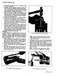
 Next
Next
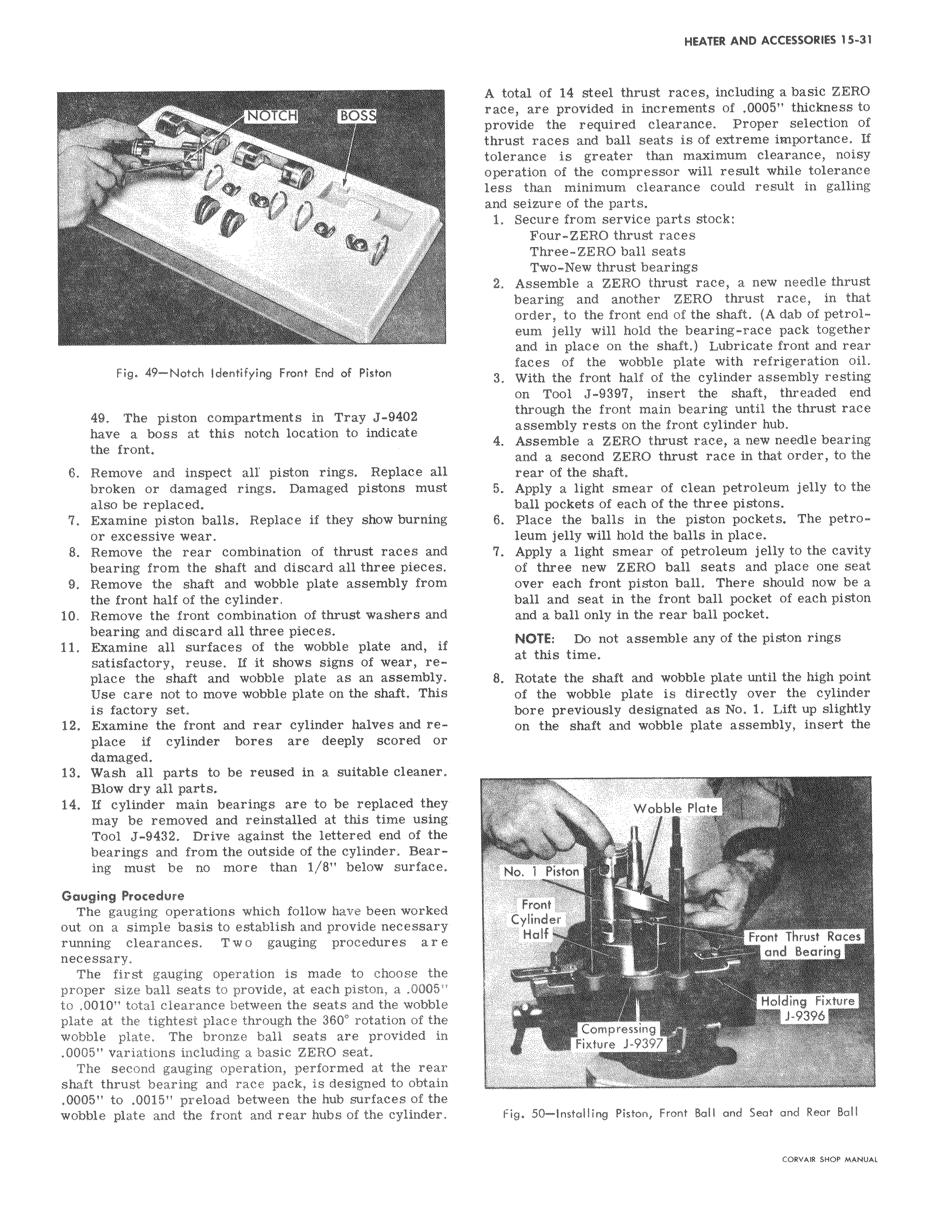
H BOSS Fig 49 Notch Identifying Front End of Piston 49 The piston compartments in Tray J 9402 have a boss at this notch location to indicate the front 6 Remove and inspect all piston rings Replace all broken or damaged rings Damaged pistons must also be replaced 7 Examine piston balls Replace if they show burning or excessive wear 8 Remove the rear combination of thrust races and bearing from the shaft and discard all three pieces 9 Remove the shaft and wobble plate assembly from the front half of the cylinder 10 Remove the front combination of thrust washers and bearing and discard all three pieces 11 Examine all surfaces of the wobble plate and if satisfactory reuse If it shows signs of wear replace the shaft and wobble plate as an assembly Use care not to move wobble plate on the shaft This is factory set 12 Examine the front and rear cylinder halves and replace if cylinder bores are deeply scored or damaged 13 Wash all parts to be reused in a suitable cleaner Blow dry all parts 14 If cylinder main bearings are to be replaced they may be removed and reinstalled at this time using Tool J 9432 Drive against the lettered end of the bearings and from the outside of the cylinder Bearing must be no more than 1 8 below surface Gauging Procedure The gauging operations which follow have been worked out on a simple basis to establish and provide necessary running clearances Two gauging procedures are necessary The first gauging operation is made to choose the proper size ball seats to provide at each piston a 0005 to 0010 total clearance between the seats and the wobble plate at the tightest place through the 360 rotation of the wobble plate The bronze ball seats are provided in 0005 variations including a basic ZERO seat The second gauging operation performed at the rear shaft thrust bearing and race pack is designed to obtain 0005 to 0015 preload between the hub surfaces of the wobble plate and the front and rear hubs of the cylinder A total of 14 steel thrust races including a basic ZERO race are provided in increments of 0005 thickness to provide the required clearance Proper selection of thrust races and ball seats is of extreme importance If tolerance is greater than maximum clearance noisy operation of the compressor will result while tolerance less than minimum clearance could result in galling and seizure of the parts 1 Secure from service parts stock Four ZERO thrust races Three ZERO ball seats Two New thrust bearings 2 Assemble a ZERO thrust race a new needle thrust bearing and another ZERO thrust race in that order to the front end of the shaft A dab of petrol eum jelly will hold the bearing race pack together and in place on the shaft Lubricate front and rear faces of the wobble plate with refrigeration oil 3 With the front half of the cylinder assembly resting on Tool J 939 insert the shaft threaded end through the front main bearing until the thrust race assembly rests on the front cylinder hub 4 Assemble a ZERO thrust race a new needle bearing and a second ZERO thrust race in that order to the rear of the shaft 5 Apply a light smear of clean petroleum jelly to the ball pockets of each of the three pistons 6 Place the balls in the piston pockets The petroleum jelly will hold the balls in place 7 Apply a light smear of petroleum jelly to the cavity of three new ZERO ball seats and place one seat over each front piston ball There should now be a ball and seat in the front ball pocket of each piston and a ball only in the rear ball pocket NOTE Do not assemble any of the piston rings at this time 8 Rotate the shaft and wobble plate until the high point of the wobble plate is directly over the cylinder bore previously designated as No 1 Lift up slightly on the shaft and wobble plate assembly insert the Wobble Plate k No 1 Piston Front Cylinder M Half Fr nt T rust Races 0 nnd Beorin Holding Fixture J 9396 Compressing Fixture 1 9397 Fig 50 Installing Piston Front Ball and Seat and Rear Ball CCNtVAIR SHOP MANUAL