Jeep Parts Wiki | Ford Parts Wiki
Home | Search | Browse
|
Corvair Chassis Shop Manual December 1964 |
|
Prev
 Next
Next
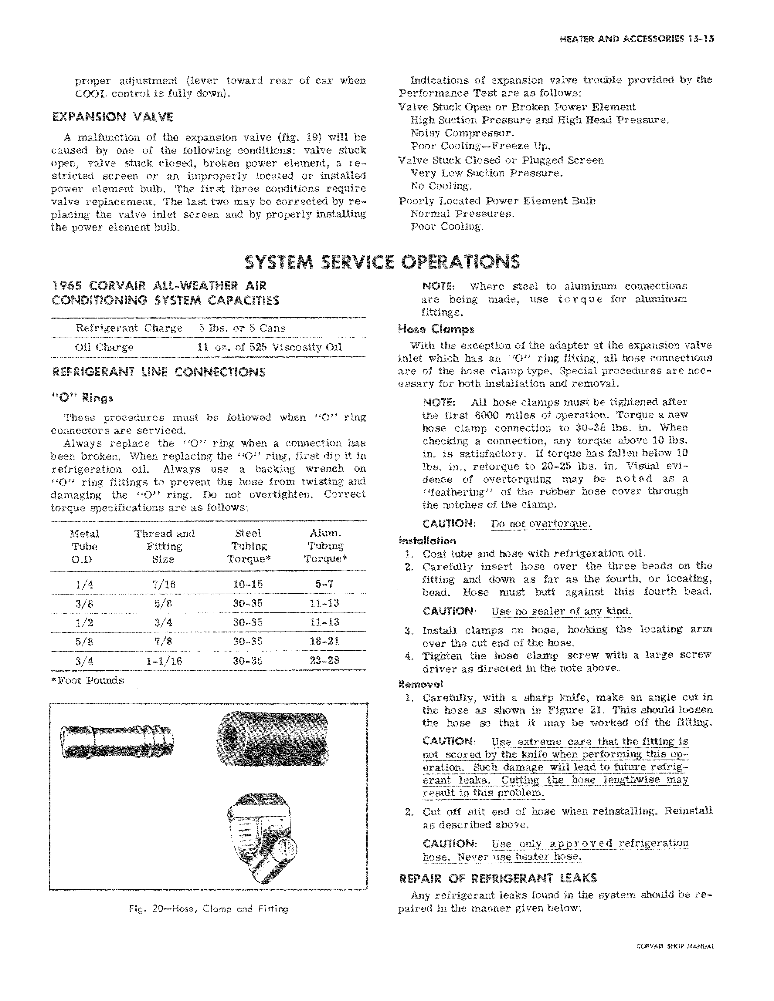
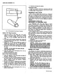
proper adjustment lever toward rear of car when COOL control is fully down EXPANSION VALVE A malfunction of the expansion valve fig 19 will be caused by one of the following conditions valve stuck open valve stuck closed broken power element a restricted screen or an improperly located or installed power element bulb The first three conditions require valve replacement The last two may be corrected by replacing the valve inlet screen and by properly installing the power element bulb SYSTEM SERVI 1965 CORVAIR ALL WEATHER AIR CONDITIONING SYSTEM CAPACITIES Refrigerant Charge 5 lbs or 5 Cans Oil Charge 11 oz of 525 Viscosity Oil REFRIGERANT LINE CONNECTIONS O Rings These procedures must be followed when 1 O ring connectors are serviced Always replace the 1O ring when a connection has been broken When replacing the O ring first dip it in refrigeration oil Always use a backing wrench on 11011 ring fittings to prevent the hose from twisting and damaging the O ring Do not overtighten Correct torque specifications are as follows Metal Thread and Steel Alum Tube Fitting Tubing Tubing O D Size Torque Torque 1 4 7 16 10 15 5 7 3 8 5 8 30 35 11 13 1 2 3 4 30 35 11 13 5 8 7 8 30 35 18 21 3 4 1 1 18 30 35 23 28 Foot Pounds i a AMEML Fig 20 Hose Clamp and Fitting Indications of expansion valve trouble provided by the Performance Test are as follows Valve Stuck Open or Broken Power Element High Suction Pressure and High Head Pressure Noisy Compressor Poor Cooling Freeze Up Valve Stuck Closed or Plugged Screen Very Low Suction Pressure No Cooling Poorly Located Power Element Bulb Normal Pressures Poor Cooling CE OPERATIONS NOTE Where steel to aluminum connections are being made use torque for aluminum fittings Hose Clamps With the exception of the adapter at the expansion valve inlet which has an O ring fitting all hose connections are of the hose clamp type Special procedures are necessary for both installation and removal NOTE All hose clamps must be tightened after the first 6000 miles of operation Torque a new hose clamp connection to 30 38 lbs in When checking a connection any torque above 10 lbs in is satisfactory If torque has fallen below 10 lbs in retorque to 20 25 lbs in Visual evidence of overtorquing may be noted as a feathering of the rubber hose cover through the notches of the clamp CAUTION Do not overtorque Installation 1 Coat tube and hose with refrigeration oil 2 Carefully insert hose over the three beads on the fitting and down as far as the fourth or locating bead Hose must butt against this fourth bead CAUTION Use no sealer of any kind 3 Install clamps on hose hooking the locating arm over the cut end of the lose 4 Tighten the hose clamp screw with a large screw driver as directed in the note above Removal 1 Carefully with a sharp knife make an angle cut in the hose as shown in Figure 21 This should loosen the hose so that it may be worked off the fitting CAUTION Use extreme care that the fitting is not scored by the knife when performing this operation Such damage will lead to future refrigerant leaks Cutting the hose lengthwise may result in this problem 2 Cut off slit end of hose when reinstalling Reinstall as described above CAUTION Use only approved refrigeration hose Never use heater hose REPAIR OF REFRIGERANT LEAKS Any refrigerant leaks found in the system should be repaired in the manner given below