Jeep Parts Wiki | Ford Parts Wiki
Home | Search | Browse
|
Corvair Chassis Shop Manual December 1964 |
|
Prev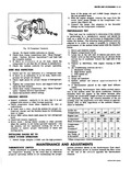
 Next
Next
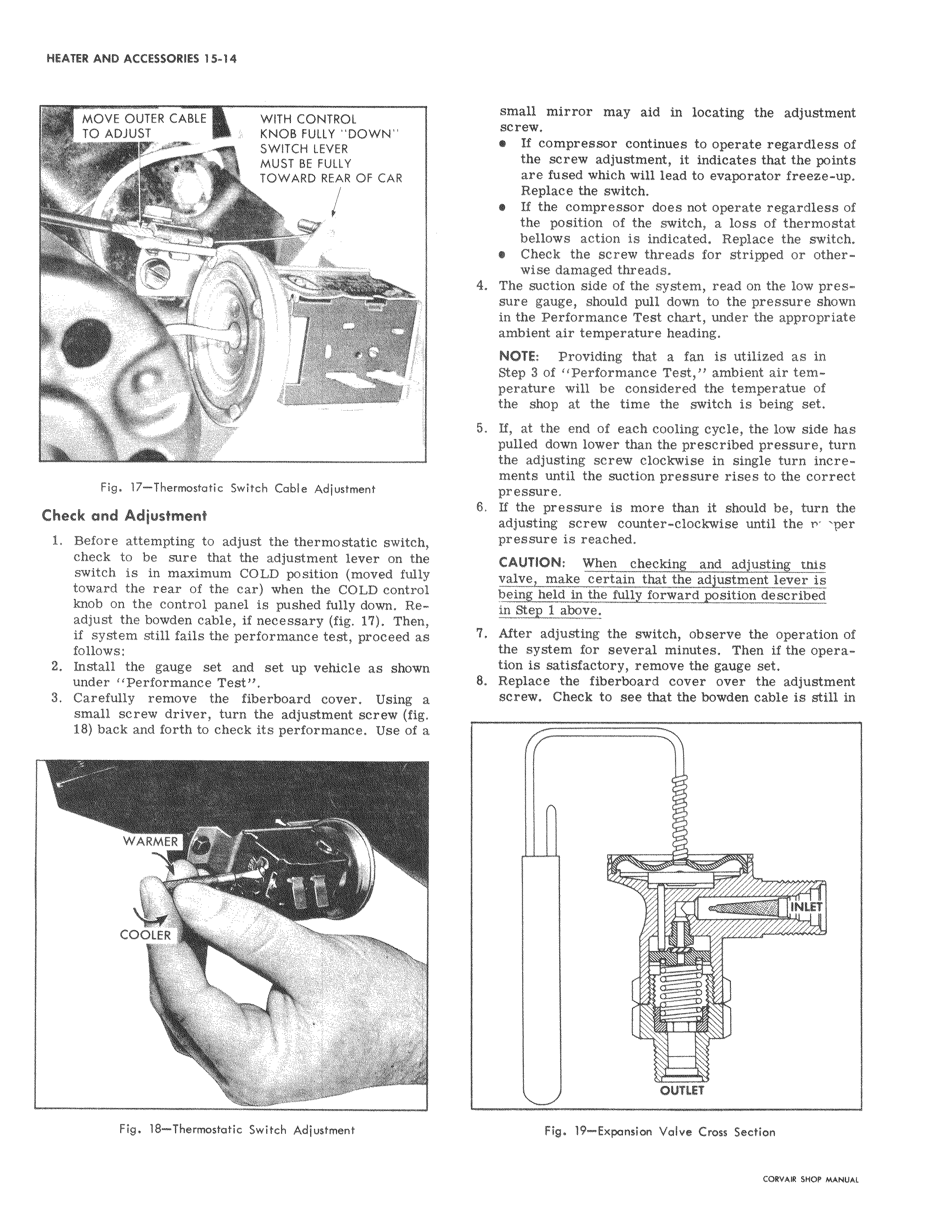
MOVE OUTER CABLE WITH CONTROL I TO ADJUST KNOB FULLY DOWN SWITCH LEVER MUST BE FULLY TOWARD REAR OF CAR Fig 17 Thermostatic Switch Cable Adjustment Check and Adjustment 1 Before attempting to adjust the thermostatic switch check to be sure that the adjustment lever on the switch is in maximum COLD position moved fully toward the rear of the car when the COLD control knob on the control panel is pushed fully down Readjust the bowden cable if necessary fig 17 Then if system still fails the performance test proceed as follows 2 Install the gauge set and set up vehicle as shown under Performance Test 3 Carefully remove the fiberboard cover Using a small screw driver turn the adjustment screw fig 18 back and forth to check its performance Use of a i WARMER I COOLER J 1 K 1 Fig 18 Thermostatic Switch Adjustment small mirror may aid in locating the adjustment screw If compressor continues to operate regardless of the screw adjustment it indicates that the points are fused which will lead to evaporator freeze up Replace the switch e If the compressor does not operate regardless of the position of the switch a loss of thermostat bellows action is indicated Replace the switch 6Check the screw threads for stripped or otherwise damaged threads 4 The suction side of the system read on the low pressure gauge should pull down to the pressure shown in the Performance Test chart under the appropriate ambient air temperature heading NOTE Providing that a fan is utilized as in Step 3 of Performance Test ambient air temperature will be considered the temperatue of the shop at the time the switch is being set 5 If at the end of each cooling cycle the low side has pulled down lower than the prescribed pressure turn the adjusting screw clockwise in single turn incre mehts until the suction pressure rises to the correct pressure 6 If the pressure is more than it should be turn the adjusting screw counter clockwise until the nr per pressure is reached CAUTION When checking and adjusting tnis valve make certain that the adjustment lever is being held in the fully forward position described in Step 1 above 7 After adjusting the switch observe the operation of the system for several minutes Then if the operation is satisfactory remove the gauge set 8 Replace the fiberboard cover over the adjustment screw Check to see that the bowden cable is still in i fl I 1 INLET OUTLET Fig 19 Expansion Valve Cross Section