Jeep Parts Wiki | Ford Parts Wiki
Home | Search | Browse
|
Corvair Chassis Shop Manual December 1964 |
|
Prev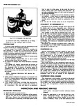
 Next
Next
Fig 16 Compressor Connector charge No liquid visible indicates no charge 4 Check hose clamp connections see Hose Clamps under System Service Operations and leak test the complete system 5 If there is evidence of an oil leak check the compressor to see that the oil charge is satisfactory 6 Check the system controls for proper operation 6000 MILE INSPECTION 1 Check unit for any indication of a refrigerant leak 2 If there is an indication of an oil leak check compressor for proper oil charge 3 Check sight glass for proper charge of Refrigerant12 4 Tighten the compressor brace and support bolts and check the belt tension 5 Check hose clamp connections See Hose Clamps under System Service Operations 6 Check thermostatic switch setting PERIODIC SERVICE Inspect condenser regularly to be sure that it is not plugged with leaves or other foreign material Check evaporator drain tubes regularly for dirt or restrictions At least once a year check the system for proper refrigerant charge and the flexible hoses for brittleness wear or leaks Every 6000 miles check sight glass for low refrigerant level Check belt tension regularly Every week during winter months or other periods when the system is not being operated regularly ruh the system set for maximum cooling for 10 or 15 minutes to insure proper lubrication of seals and moving parts INSTALLING GAUGE SET TO CHECK SYSTEM OPERATION 1 Install Gauge Adapter J 5420 onto the high pressure MAINTENANCE I THERMOSTATIC SWITCH Some adjustment is possible on this switch located on the evaporator housing in the event that an otherwise properly operating switch is not maintaining the proper hose of the gauge set and J 9459 Gauge Adapter on the low pressure hose 2 With the engine stopped remove the caps from the cored valve gauge fittings on the compressor connector See Figure 16 3 Connect the gauge line adapters to the threaded fittings on the compressor connector PERFORMANCE TEST This test may be conducted to determine if the system is performing in a satisfactory manner and should be used as a guide by the serviceman in diagnosing trouble within the system The following fixed onditions must be adhered to in order to make it possible to compare the performance of the system being tested with the standard below 1 Doors and windows closed 2 Engine compartment lid up 3 Large fan at the left side of vehicle just above rear fender level so that during tests fan air stream flows across top of condenser toward the right side of the vehicle 4 Vehicle in NEUTRAL with engine running at 2000 rpm 5 Air Conditioning controls set fora Maximum cooling b High blower speed c Full inside air 6 Heater off 7 Gauge set installed 8 System settled out run in approximately 10 minutes 9 A thermometer placed in the right hand diffuser outlet The following Performance Data define normal operation of the system under the above conditions Relative humidity does not appear in the tables because after running the prescribed length of time on recirculated air and maximum cooling the relative humidity of the air passing over the evaporator core will remain at approximately 35 b to 40 regardless of the ambient temperature or humidity Grille Air Temperature 70 800 90 1000 110 1200 Engine rpm 2000 Compressor 150 165 205 220 265 295Head Pressure 160 175 215 230 275 305 Compressor Suction Pressure 10 11 13 14 17 19 Discharge Air Temp at 34 36 38 38 39 40 R H Outlet 40 41 43 43 44 45 When compressor clutch disengages kND ADJUSTMENTS suction pressure shown in the Performance Test chart The adjustment screw is located beneath the fiber cover on the end of the switch opposite the thermostatic element