Jeep Parts Wiki | Ford Parts Wiki
Home | Search | Browse
|
Corvair Chassis Shop Manual December 1964 |
|
Prev
 Next
Next
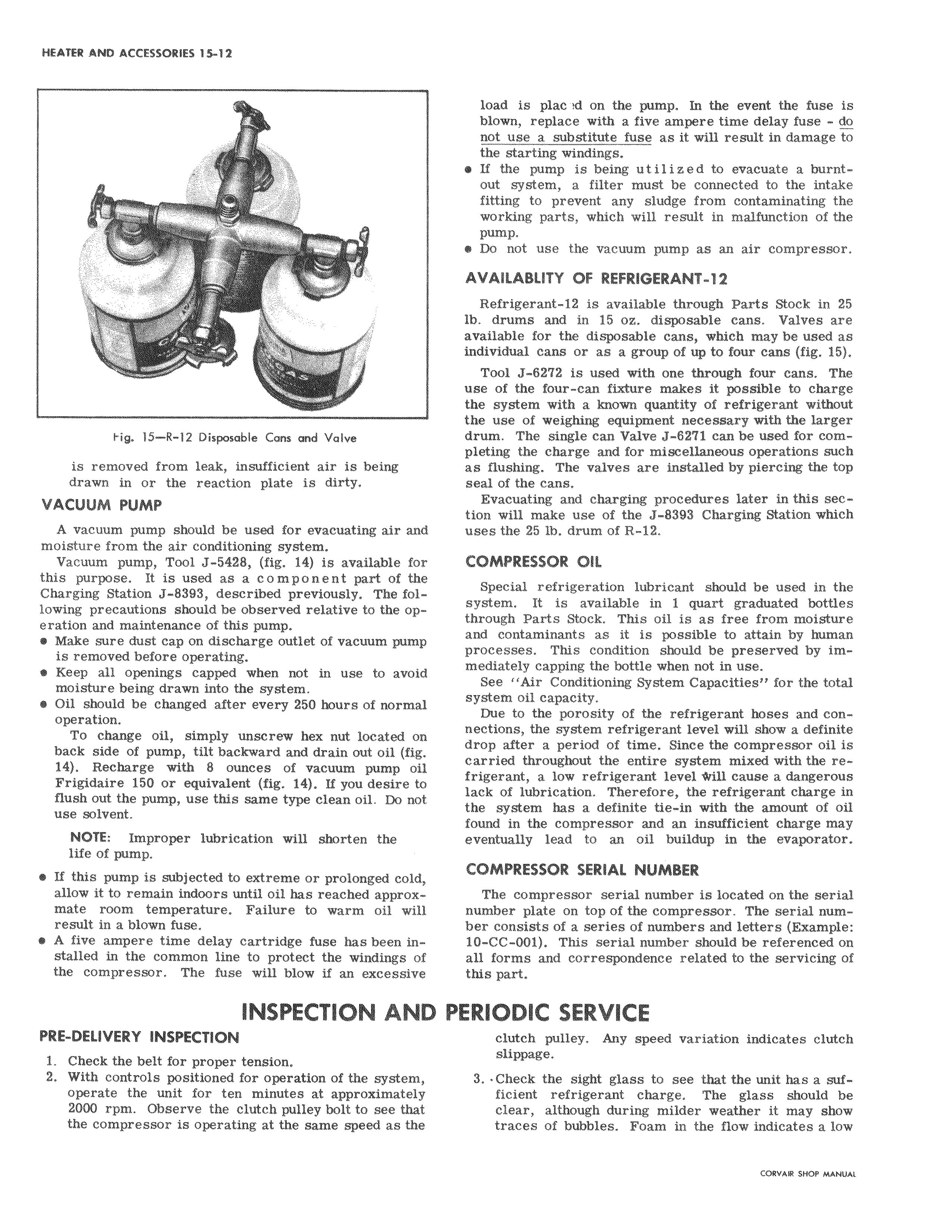
s Fig 15 R 12 Disposable Cons and Valve is removed from leak insufficient air is being drawn in or the reaction plate is dirty VACUUM PUMP A vacuum pump should be used for evacuating air an moisture from the air conditioning system Vacuum pump Tool J 5428 fig 14 is available fo this purpose It is used as a component part of the Charging Station J 8393 described previously The following precautions should be observed relative to the op eration and maintenance of this pump Make sure dust cap on discharge outlet of vacuum pum is removed before operating Keep all openings capped when not in use to avoid moisture being drawn into the system Oil should be changed after every 250 hours of norma l operation To change oil simply unscrew hex nut located on back side of pump tilt backward and drain out oil fig 14 Recharge with 8 ounces of vacuum pump oil Frigidaire 150 or equivalent fig 14 If you desire flush out the pump use this same type clean oil Do I n use solvent NOTE Improper lubrication will shorten the life of pump e If this pump is subjected to extreme or prolonged coic allow it to remain indoors until oil has reached appro x mate room temperature Failure to warm oil will result in a blown fuse e A five ampere time delay cartridge fuse has been installed in the common line to protect the windings f the compressor The fuse will blow if an excessive INSPECTION AND F PRE DELIVERY INSPECTION 1 Check the belt for proper tension 2 With controls positioned for operation of the system operate the unit for ten minutes at approximately 2000 rpm Observe the clutch pulley bolt to see that the compressor is operating at the same speed as th load s plac d on the pump In the event the fuse is blown replace with a five ampere time delay fuse do not use a substitute fuse as it will result in damage to the starting windings If the pump is being utilized to evacuate a burntout system a filter must be connected to the intake fitting to prevent any sludge from contaminating the workiiig parts which will result in malfunction of the PUMP Do not use the vacuum pump as an air compressor AVAILABLITY OF REFRIGERANT 12 Refrigerant 12 is available through Parts Stock in 25 lb drums and in 15 oz disposable cans Valves are available for the disposable cans which may be used as individual cans or as a group of up to four cans fig 15 Tool J 6272 is used with one through four cans The use of the four can fixture makes it possible to charge the system with a known quantity of refrigerant without the use of weighing equipment necessary with the larger drum The single can Valve J 6271 can be used for completing the charge and for miscellaneous operations such as flushing The valves are installed by piercing the top seal of the cans Evacuating and charging procedures later in this section will make use of the J 8393 Charging Station which uses the 25 lb drum of R 12 COMPRESSOR OIL Special refrigeration lubricant should be used in the system It is available in 1 quart graduated bottles throughlParts Stock This oil is as free from moisture and contaminants as it is possible to attain by human processes This condition should be preserved by immediately capping the bottle when not in use See Air Conditioning System Capacities for the total system oil capacity Due to the porosity of the refrigerant hoses and connections the system refrigerant level will show a definite drop after a period of time Since the compressor oil is carried throughout the entire system mixed with the refrigerant a low refrigerant level drill cause a dangerous lack of jlubrication Therefore the refrigerant charge in the system has a definite tie in with the amount of oil found in the compressor and an insufficient charge may eventually lead to an oil buildup in the evaporator COMPRESSOR SERIAL NUMBER The compressor serial number is located on the serial number plate on top of the compressor The serial number consists of a series of numbers and letters Example 10 CC 001 This serial number should be referenced on all forms and correspondence related to the servicing of this part ERIODIC SERVICE clutch pulley Any speed variation indicates clutch slippage 3 Check the sight glass to see that the unit has a sufficient refrigerant charge The glass should be clear although during milder weather it may show traces of bubbles Foam in the flow indicates a low