Jeep Parts Wiki | Ford Parts Wiki
Home | Search | Browse
|
Corvair Chassis Shop Manual December 1964 |
|
Prev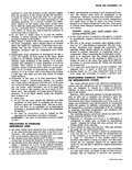
 Next
Next
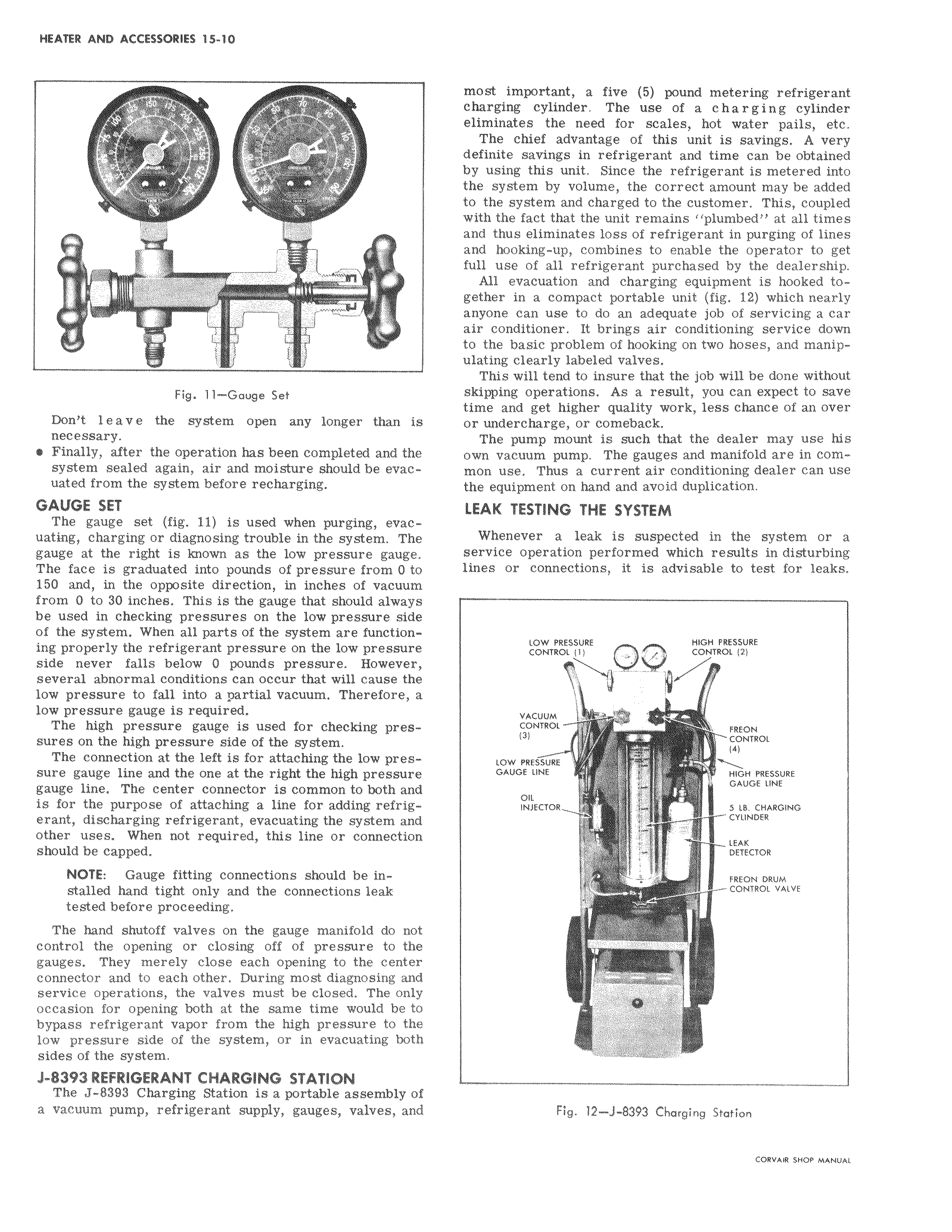
Fig 11 Gauge Set Don t leave the system open any longer than is necessary I Finally after the operation has been completed and the system sealed again air and moisture should be evacuated from the system before recharging GAUGE SET The gauge set fig 11 is used when purging evacuating charging or diagnosing trouble in the system The gauge at the right is known as the low pressure gauge The face is graduated into pounds of pressure from 0 to 150 and in the opposite direction in inches of vacuum from 0 to 30 inches This is the gauge that should always be used in checking pressures on the low pressure side of the system When all parts of the system are functioning properly the refrigerant pressure on the low pressure side never falls below 0 pounds pressure However 1 several abnormal conditions can occur that will cause the low pressure to fall into a uartiai vacuum Therefore a low pressure gauge is required The high pressure gauge is used for checking pres i sures on the high pressure side of the system The connection at the left is for attaching the low pres I sure gauge line and the one at the right the high pressur gauge line The center connector is common to both and is for the purpose of attaching a line for adding refrigerant discharging refrigerant evacuating the system and other uses When not required this line or connection should be capped NOTE Gauge fitting connections should be in stalled hand tight only and the connections leak tested before proceeding The hand shutoff valves on the gauge manifold do not control the opening or closing off of pressure to the gauges They merely close each opening to the cente connector and to each other During most diagnosing an service operations the valves must be closed The onl occasion for opening both at the same time would be t bypass refrigerant vapor from the high pressure to the low pressure side of the system or in evacuating both sides of the system J 8393 REFRIGERANT CHARGING STATION The J 8393 Charging Station is a portable assembly o a vacuum pump refrigerant supply gauges valves and most important a five 5 pound metering refrigerant charging cylinder The use of a charging cylinder eliminates the need for scales hot water pails etc The chief advantage of this unit is savings A very definite savings in refrigerant and time can be obtained by using this unit Since the refrigerant is metered into the system by volume the correct amount may be added to the system and charged to the customer This coupled with the fact that the unit remains plumbed at all times and thus eliminates loss of refrigerant in purging of lines and hooking up combines to enable the operator to get full use of all refrigerant purchased by the dealership All evacuation and charging equipment is hooked together in a compact portable unit fig 12 which nearly anyone can use to do an adequate job of servicing a car air conditioner It brings air conditioning service down to the basic problem of hooking on two hoses and manipulating clearly labeled valves This will tend to insure that the job will be done without skipping operations As a result you can expect to save time and get higher quality work less chance of an over or undercharge or comeback The pump mount is such that the dealer may use his own vacuum pump The gauges and manifold are in common use Thus a current air conditioning dealer can use the equipment on hand and avoid duplication LEAK TESTING THE SYSTEM Whenever a leak is suspected in the system or a service operation performed which results in disturbing lines or connections it is advisable to test for leaks j LOW PRESSURE HIGH CONTROLS 2 RE 1 CONTROL 1 VACUUM CONTROL FREON CONTROL 4 LOW 1 PRESSURE GAUGE LINE HIGH PRESSURE GAUGE LINE OIL INJECTOR 5 L8 CHARGING CYLINDER LEAK DETECTOR FREON DRUM t CONTROL VALVE rL Fig 12 J 8393 Charging Station