Jeep Parts Wiki | Ford Parts Wiki
Home | Search | Browse
|
Corvair Chassis Shop Manual December 1964 |
|
Prev

 Next
Next
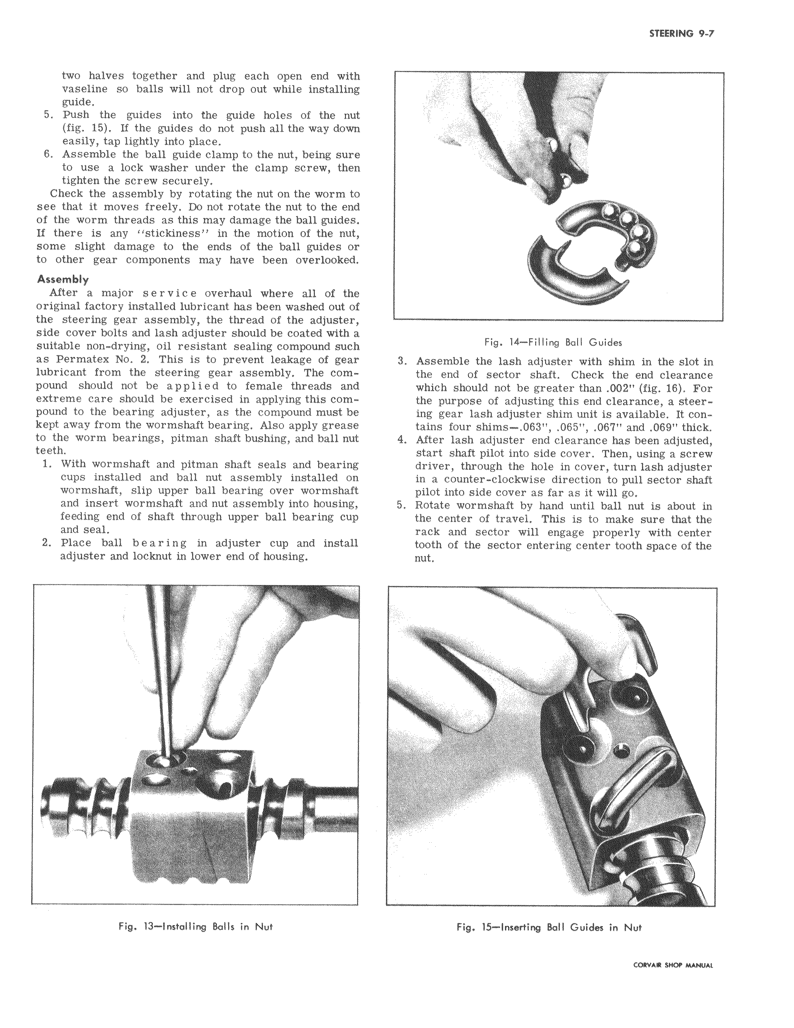
two halves together and plug each open end with vaseline so balls will not drop out while installing guide 5 Push the guides into the guide holes of the nut fig 15 If the guides do not push all the way down easily tap lightly into place 6 Assemble the ball guide clamp to the nut being sure to use a lock washer under the clamp screw then tighten the screw securely Check the assembly by rotating the nut on the worm to see that it moves freely Do not rotate the nut to the end of the worm threads as this may damage the ball guides If there is any stickiness in the motion of the nut some slight damage to the ends of the ball guides or to other gear components may have been overlooked Assembly After a major Service overhaul where all of the original factory installed lubricant has been washed out of the steering gear assembly the thread of the adjuster side cover bolts and lash adjuster should be coated with a suitable non drying oil resistant sealing compound such as Permatex No 2 This is to prevent leakage of gear lubricant from the steering gear assembly The compound should not be applied to female threads and extreme care should be exercised in applying this compound to the bearing adjuster as the compound must be kept away from the wormshaft bearing Also apply grease to the worm bearings pitman shaft bushing and ball nut teeth 1 With wormshaft and pitman shaft seals and bearing cups installed and ball nut assembly installed on wormshaft slip upper ball bearing over wormshaft and insert wormshaft and nut assembly into housing feeding end of shaft through upper ball bearing cup and seal 2 Place ball bearing in adjuster cup and install adjuster and locknut in lower end of housing ELI Fig 13 installing Balls in Nut x Fig 14 Filling Ball Guides 3 Assemble the lash adjuster with shim in the slot in the end of sector shaft Check the end clearance which should not be greater than 002 fig 16 For the purpose of adjusting this end clearance a steering gear lash adjuster shim unit is available It contains four shims 063 065 067 and 069 thick 4 After lash adjuster end clearance has been adjusted start shaft pilot into side cover Then using a screw driver through the hole in cover turn lash adjuster in a counter clockwise direction to pull sector shaft pilot into side cover as far as it will go 5 Rotate wormshaft by hand until ball nut is about in the center of travel This is to make sure that the rack and sector will engage properly with center tooth of the sector entering center tooth space of the nut ry F y4 k Fig 15 Inserting Ball Guides in Nut CORVAR SOW MAMlAt

 Next
Next