Jeep Parts Wiki | Ford Parts Wiki
Home | Search | Browse | Marketplace | Messages | FAQ | Guest
|
Corvair Chassis Shop Manual December 1964 |
|
Prev

 Next
Next
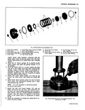
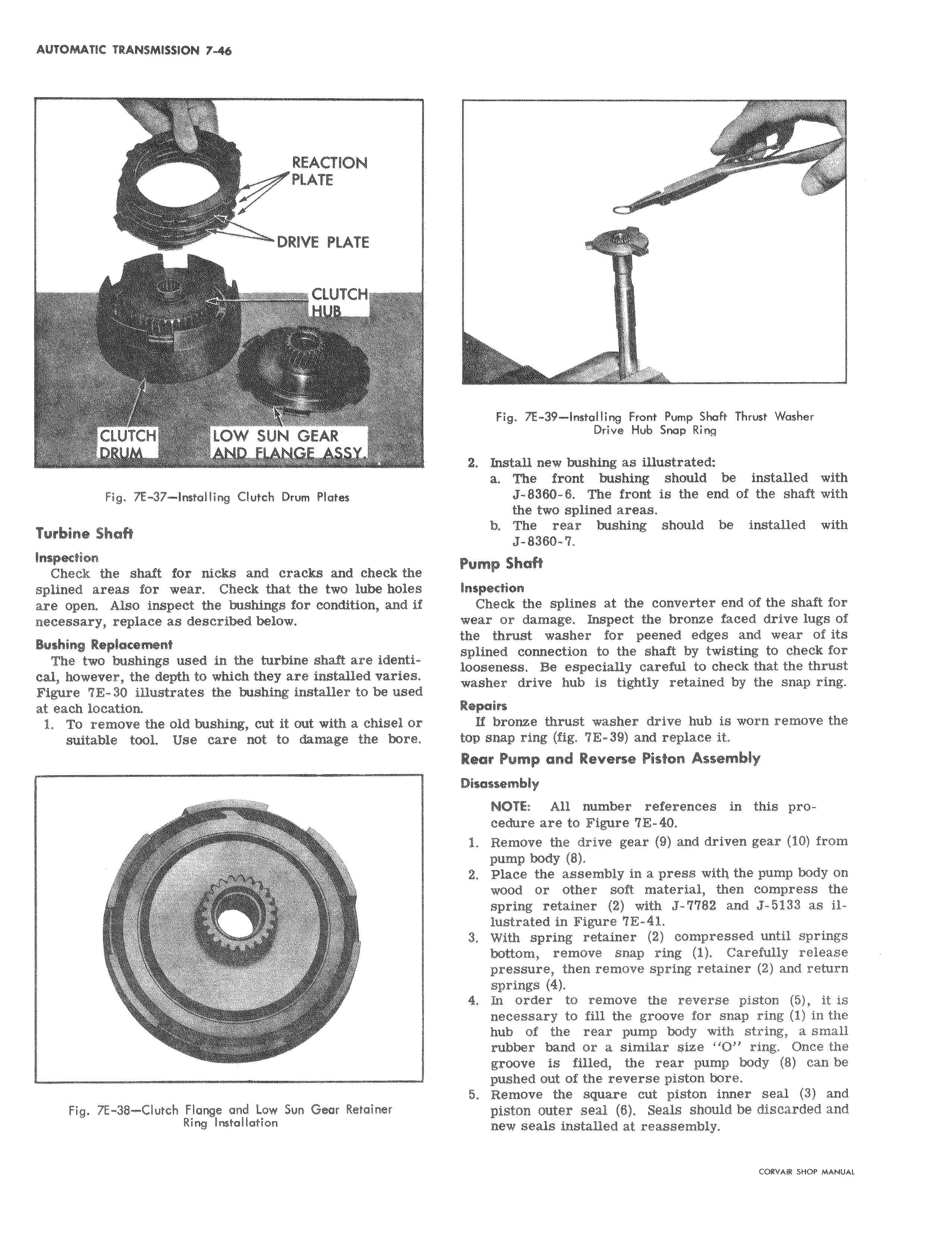
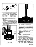
REACTION PLATE DRIVE PLATE CIUTCH CLUTCH LOW SUN GEARFig A 37 Instal ling Clutch Drum Plates Turbine Shaft Inspection Check the shaft for nicks and cracks and check the splined areas for wear Check that the two lube holes are open Also inspect the bushings for condition and i necessary replace as described below Bushing Replacement The two bushings used in the turbine shaft are identi cal however the depth to which they are installed varie Figure 7E 30 illustrates the bushing installer to be used at each location 1 To remove the old bushing cut it out with a chisel or suitable tool Use care not to damage the bore I a Fig 7E 38 Clutch Flange and Low Sun Gear Retainer Ring Installation Fig 7E 39 Installing Front Pump Shaft Thrust Washer Drive Hub Snap Ring 2 Install new bushing as illustrated a The front bushing should be installed with J 8360 8 The front is the end of the shaft with the two splined areas b The rear bushing should be installed with 7 8380 7 Pump Shaft Inspection Check the splines at the converter end of the shaft for wear or damage Inspect the bronze faced drive lugs of the thrust washer for peened edges and wear of its splined connection to the shaft by twisting to check for loosen0s Be especially careful to check that the thrust washer I drive hub is tightly retained by the snap ring Repoin i If bronze thrust washer drive hub is worn remove the top snap ring fig 7E 39 and replace it Rear Pomp and Reverse Piston Assembly Disassembly NOTE All number references in this procedure are to Figure 7E 40 1 Remove the drive gear 9 and driven gear 10 from pump body 8 2 PLalce the assembly in a press with the pump body on wood or other soft material then compress the spring retainer 2 with J 7782 and J 5133 as illustrated in Figure 7E 41 3 With spring retainer 2 compressed until springs bottom remove snap ring 1 Carefully release pressure then remove spring retainer 2 and return springs 4 4 In order to remove the reverse piston 5 it is nedessary to fill the groove for snap ring 1 in the hub of the rear pump body with string a small rubber band or a similar size O ring Once the groove is filled the rear pump body 8 can be pushed out of the reverse piston bore 5 Remove the square cut piston inner seal 3 and piston outer seal 6 Seals should be discarded and new seals installed at reassembly

 Next
Next