Jeep Parts Wiki | Ford Parts Wiki
Home | Search | Browse | Marketplace | Messages | FAQ | Guest
|
Corvair Chassis Shop Manual December 1964 |
|
Prev

 Next
Next
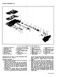
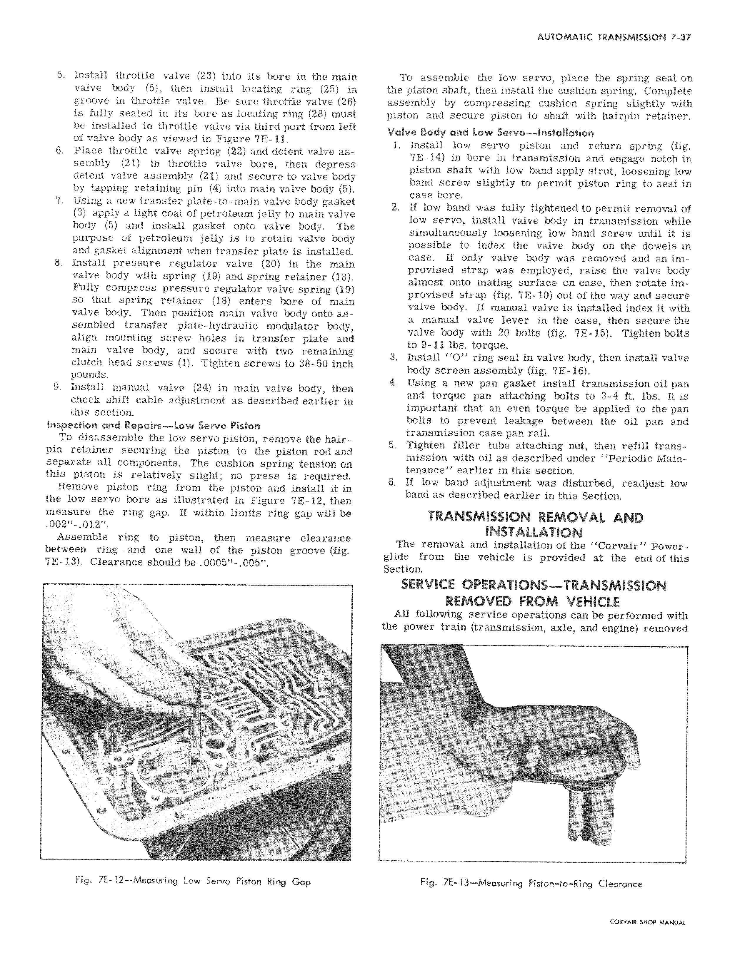
5 Install throttle valve 23 into its bore in the main valve body 5 then install locating ring 25 in groove in throttle valve Be sure throttle valve 26 is fully seated in its bore as locating ring 28 must be installed in throttle valve via third port from left of valve body as viewed in Figure 7E 11 6 Place throttle valve spring 22 and detent valve assembly 21 in throttle valve bore then depress detent valve assembly 21 and secure to valve body by tapping retaining pin 4 into main valve body 5 7 Using a new transfer plate to main valve body gasket 3 apply a light coat of petroleum jelly to main valve body 5 and install gasket onto valve body The purpose of petroleum jelly is to retain valve body and gasket alignment when transfer plate is installed 8 Install pressure regulator valve 20 in the main valve body with spring 19 and spring retainer 18 Fully compress pressure regulator valve spring 19 so that spring retainer 18 enters bore of main valve body Then position main valve body onto assembled transfer plate hydraulic modulator body align mounting screw holes in transfer plate and main valve body and secure with two remaining clutch head screws 1 Tighten screws to 38 50 inch pounds 9 Install manual valve 24 in main valve body then check shift cable adjustment as described earlier in this section Inspection and Repairs Low Servo Piston To disassemble the low servo piston remove the hairpin retainer securing the piston to the piston rod and separate all components The cushion spring tension on this piston is relatively slight no press is required Remove piston ring from the piston and install it in the low servo bore as illustrated in Figure 7E 12 then measure the ring gap If within limits ring gap will be 00211 01211 Assemble ring to piston then measure clearance between ring and one wall of the piston groove fig 7E 13 Clearance should be 0005 005 To assemble the low servo place the spring seat on the piston shaft then install the cushion spring Complete assembly by compressing cushion spring slightly with piston and secure piston to shaft with hairpin retainer Valve Body and Low Servo Installation 1 Install low servo piston and return spring fig 7E 14 in bore in transmission and engage notch in piston shaft with low band apply strut loosening low band screw slightly to permit piston ring to seat in case bore 2 If low band was fully tightened to permit removal of low servo install valve body in transmission while simultaneously loosening low band screw until it is possible to index the valve body on the dowels in case If only valve body was removed and an improvised strap was employed raise the valve body almost onto mating surface on case then rotate improvised strap fig E 10 out of the way and secure valve body If manual valve is installed index it with a manual valve lever in the case then secure the valve body with 20 bolts fig 7E 15 Tighten bolts to 9 11 lbs torque 3 Install O ring seal in valve body then install valve body screen assembly fig 7E 16 4 Using a new pan gasket install transmission oil pan and torque pan attaching bolts to 3 4 ft lbs It is important that an even torque be applied to the pan bolts to prevent leakage between the oil pan and transmission case pan rail 5 Tighten filler tube attaching nut then refill transmission with oil as described under Periodic Maintenance earlier in this section 6 If low band adjustment was disturbed readjust low band as described earlier in this Section TRANSMISSION REMOVAL AND INSTALLATION The removal and installation of the Corvair Powerglide from the vehicle is provided at the end of this Section SERVICE OPERATIONS TRANSMISSION REMOVED FROM VEHICLE All following service operations can be performed with the power train transmission axle and engine removed

 Next
Next