Jeep Parts Wiki | Ford Parts Wiki
Home | Search | Browse
|
Corvair Chassis Shop Manual December 1964 |
|
Prev

 Next
Next
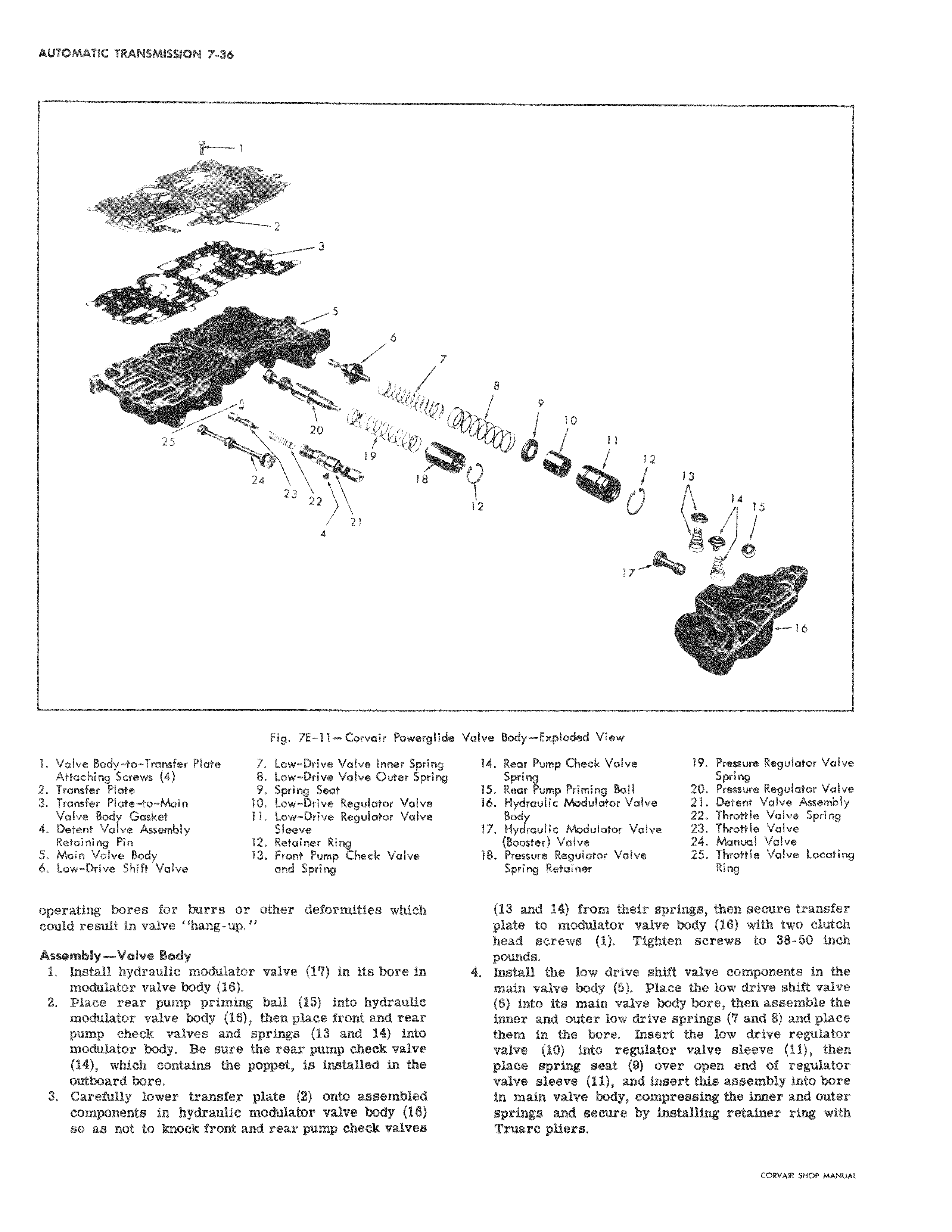
sAllrl 1 T 2 I 3 S 6 7 4 7 25 20 N4 19 24 I 8 23 22 21 I 4 I Fig 7E 1 Corvair Pow erglide 1 Valve Body to Transfer Plate 7 Low Drive Valve Inner S I nng cttaehingSerews 4 8 Low Drive Valve Outer Spring 2 Transfer Plate 9 Spring Seat 3 Transfer Plate to Nbin 10 Low Drive Regulator Volvo Valve Body Gasket 11 Low Drive Regulator V qlve 4 Detent Valve Assembly Sleeve Retaining Pin 12 Retainer Ring 5 Main Valve Body 13 Front Pump Check Valvjs b Low Drive Shift Valve and Spring operating bores for burrs or other deformities which could result in valve hang up Assembly Valve Body 1 Install hydraulic modulator valve i in its bore In modulator valve body 16 2 Place rear pump priming ball 15 into hydra cc modulator valve body 18 then place front and r e pump check valves and springs 13 and 14 it o modulator body Be sure the rear pump cheek val e 14 which contains the poppet is installed in e outboard bore 3 Carefully lower transfer plate 2 onto assembled components in hydraulic modulator valve body 6 so as not to knock front and rear pump check valves 8 9 10 11 12 13 12 NO 0 14 15 174r 16 Valve Br1dy Exploded View 14 Roar Pump Check Valve 19 Pressure Regulator Valve 15 Re a r Pump Priming Ball 20 SPr eaaure Regulator Valve 16 Hydraulic Modulator Valve 21 Detent Valve Assembly 22 Throttle Valve Spring 17 F ydroulic Modulator Valve 23 Throttle Valve Booster Valve 24 Manual Valve 18 P ssure Regulator Volvo 25 Throttle Valve Locating S ing Retainer Ring 10 and 14 from their springs then secure transfer plalte to modulator valve body 18 with two clutch he d screws 1 Tighten screws to 38 50 inch pot nds M 4 In4tall the low drive shift valve components in the m in valve body 5 Place the low drive shift valve 8 into its main valve body bore then assemble the inrier and outer low drive springs 7 and 8 and place th4im in the bore Insert the low drive regulator va4ve 10 into regulator valve sleeve 11 then e spring seat 9 over open end of regulator e sleeve ii and insert this assembly into bore main valve body compressing the Inner and outer sp s and secure by installing retainer ring with T c pliers

 Next
Next