Jeep Parts Wiki | Ford Parts Wiki
Home | Search | Browse | Marketplace | Messages | FAQ | Guest
|
Corvair Chassis Shop Manual December 1964 |
|
Prev

 Next
Next
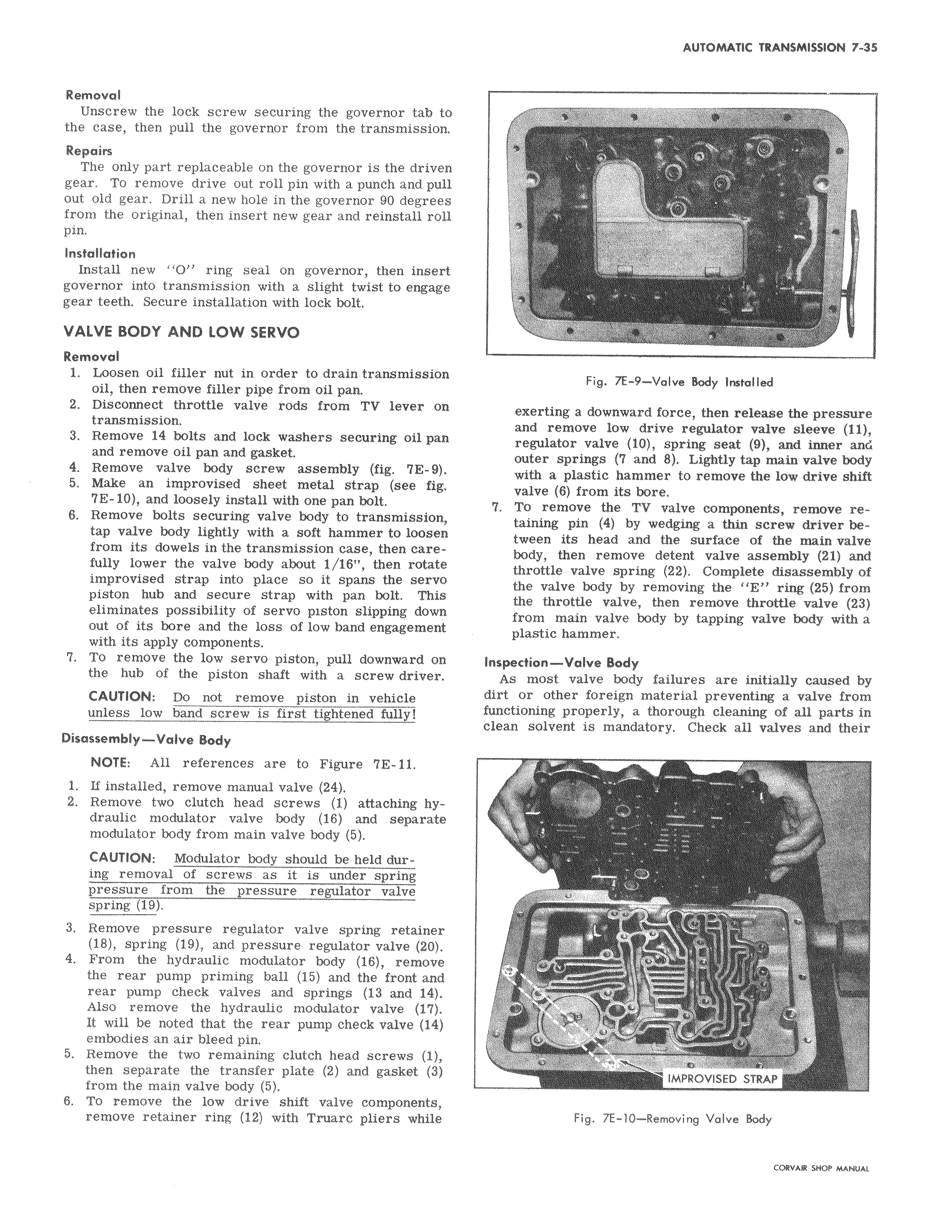
Removal Unscrew the lock screw securing the governor tab to the case then pull the governor from the transmission Repairs The only part replaceable on the governor is the driven gear To remove drive out roll pin with a punch and pull out old gear Drill a new hole in the governor 90 degrees from the original then insert new gear and reinstall roll pin Installation Install new O ring seal on governor then insert governor into transmission with a slight twist to engage gear teeth Secure installation with lock bolt VALVE BODY AND LOW SERVO Removal 1 Loosen oil filler nut in order to drain transmission oil then remove filler pipe from oil pan 2 Disconnect throttle valve rods from TV lever on transmission 3 Remove 14 bolts and lock washers securing oil pan and remove oil pan and gasket 4 Remove valve body screw assembly fig 7E 9 5 Make an improvised sheet metal strap see fig 7E 10 and loosely install with one pan bolt 6 Remove bolts securing valve body to transmission tap valve body lightly with a soft hammer to loosen from its dowels in the transmission case then carefully lower the valve body about 1 16 then rotate improvised strap into place so it spans the servo piston hub and secure strap with pan bolt This eliminates possibility of servo piston slipping down out of its bore and the loss of low band engagement with its apply components 7 To remove the low servo piston pull downward on the hub of the piston shaft with a screwdriver CAUTION Do not remove piston in vehicle unless low band screw is first tightened fullyl Disassembly Valve Body NOTE All references are to Figure 7E 11 1 If installed remove manual valve 24 2 Remove two clutch head screws 1 attaching hydraulic modulator valve body 16 and separate modulator body from main valve body 5 CAUTION Modulator body should be held during removal of screws as it is under spring pressure from the pressure regulator valve spring 19 3 Remove pressure regulator valve spring retainer 18 spring 19 and pressure regulator valve 20 4 From the hydraulic modulator body 16 remove the rear pump priming ball 15 and the front and rear pump check valves and springs 13 and 14 Also remove the hydraulic modulator valve 17 It will be noted that the rear pump check valve 14 embodies an air bleed pin 5 Remove the two remaining clutch head screws 1 then separate the transfer plate 2 and gasket 3 from the main valve body 5 6 To remove the low drive shift valve components remove retainer ring 12 with Truarc pliers while l il f f s t i f Fig 7E 9 Valve Body Installed exerting a downward force then release the pressure and remove low drive regulator valve sleeve 11 regulator valve 10 spring seat 9 and inner and outer springs and 8 Lightly tap main valve body with a plastic hammer to remove the low drive shift valve 6 from its bore 7 To remove the TV valve components remove retaining pin 4 by wedging a thin screw driver between its head and the surface of the main valve body then remove detent valve assembly 21 and throttle valve spring 22 Complete disassembly of the valve body by removing the E ring 25 from the throttle valve then remove throttle valve 23 from main valve body by tapping valve body with a plastic hammer Inspection Valve Body As most valve body failures are initially caused by dirt or other foreign material preventing a valve from functioning properly a thorough cleaning of all parts in clean solvent is mandatory Check all valves and their a I I7 r u IMPROVISED STRAP Fig 7E 10 Removing Valve Body

 Next
Next