Jeep Parts Wiki | Ford Parts Wiki
Home | Search | Browse
|
Corvair Chassis Shop Manual December 1964 |
|
Prev

 Next
Next
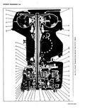
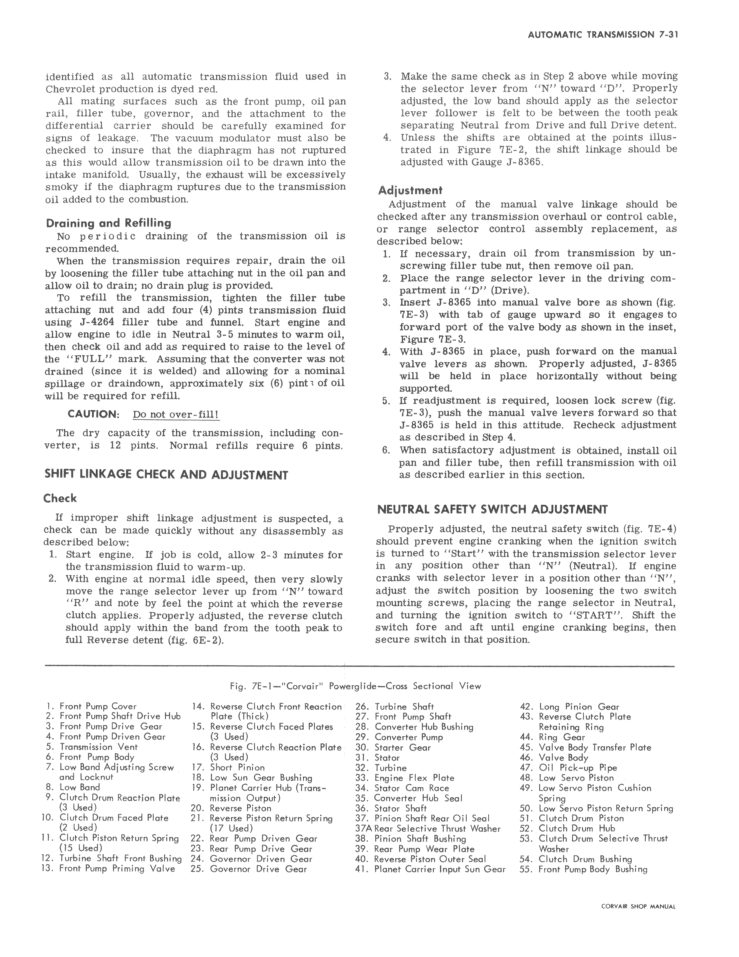
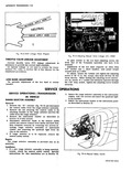
identified as all automatic transmission fluid used in Chevrolet production is dyed red All mating surfaces such as the front pump oil pan rail filler tube governor and the attachment to the differential carrier should be carefully examined for signs of leakage The vacuum modulator must also be checked to insure that the diaphragm has not ruptured as this would allow transmission oil to be drawn into the intake manifold Usually the exhaust will be excessively smoky if the diaphragm ruptures due to the transmission oil added to the combustion Draining and Refilling No p e r i o d i c draining of the transmission oil is recommended When the transmission requires repair drain the oil by loosening the filler tube attaching nut in the oil pan and allow oil to drain no drain plug is provided To refill the transmission tighten the filler tube attaching nut and add four 4 pints transmission fluid using J 4264 filler tube and funnel Start engine and allow engine to idle in Neutral 3 5 minutes to warm oil then check oil and add as required to raise to the level of the FULL mark Assuming that the converter was not drained since it is welded and allowing for a nominal spillage or draindown approximately six 6 pint l of oil will be required for refill CAUTION Do not over fill The dry capacity of the transmission including converter is 12 pints Normal refills require 6 pints SHIFT LINKAGE CHECK AND ADJUSTMENT Check If improper shift linkage adjustment is suspected a check can be made quickly without any disassembly as described below 1 Start engine If job is cold allow 2 3 minutes for the transmission fluid to warm up 2 With engine at normal idle speed then very slowly move the range selector lever up from N toward R and note by feel the point at which the reverse clutch applies Properly adjusted the reverse clutch should apply within the band from the tooth peak to full Reverse detent fig 6E 2 Fig 7E 1 Corvair Powei l Front Pump Cover 14 Reverse Clutch Front Reaction 2 Front Pump Shaft Drive Hub Plate Thick 3 Front Pump Drive Gear 15 Reverse Clutch Faced Plates 4 Front Pump Driven Gear 3 Used 5 Transmission Vent 16 Reverse Clutch Reaction Plate 6 Front Pump Body 3 Used 7 Low Band Adjusting Screw 17 Short Pinion and Locknut 18 Low Sun Gear Bushing 8 Low Band 19 Planet Carrier Hub Trans 9 Clutch Drum Reaction Plate mission Output 3 Used 20 Reverse Piston 10 Clutch Drum Faced Plate 21 Reverse Piston Return Spring 2 Used 17 Used 11 Clutch Piston Return Spring 22 Rear Pump Driven Gear 15 Used 23 Rear Pump Drive Gear 12 Turbine Shaft Front Bushing 24 Governor Driven Gear 13 Front Pump Priming Valve 25 Governor Drive Gear 3 Make the same check as in Step 2 above while moving the selector lever from N toward D Properly adjusted the low band should apply as the selector lever follower is felt to be between the tooth peak separating Neutral from Drive and full Drive detent 4 Unless the shifts are obtained at the points illustrated in Figure 7E 2 the shift linkage should be adjusted with Gauge J 8365 Adjustment Adjustment of the manual valve linkage should be checked after any transmission overhaul or control cable or range selector control assembly replacement as described below 1 If necessary drain oil from transmission by unscrewing filler tube nut then remove oil pan 2 Place the range selector lever in the driving compartment in D Drive 3 Insert J 8365 into manual valve bore as shown fig 7E 3 with tab of gauge upward so it engages to forward port of the valve body as shown in the inset Figure 7E 3 4 With J 8365 in place push forward on the manual valve levers as shown Properly adjusted J 8385 will be held in place horizontally without being supported 5 If readjustment is required loosen lock screw fig 7E 3 push the manual valve levers forward so that J 8365 is held in this attitude Recheck adjustment as described in Step 4 6 When satisfactory adjustment is obtained install oil pan and filler tube then refill transmission with oil as described earlier in this section NEUTRAL SAFETY SWITCH ADJUSTMENT Properly adjusted the neutral safety switch fig 7E 4 should prevent engine cranking when the ignition switch is turned to Start with the transmission selector lever in any position other than N Neutral If engine cranks with selector lever in a position other than N adjust the switch position by loosening the two switch mounting screws placing the range selector in Neutral and turning the ignition switch to START Shift the switch fore and aft until engine cranking begins then secure switch in that position glide Cross Sectional View 26 Turbine Shaft 42 Long Pinion Gear 27 Front Pump Shaft 43 Reverse Clutch Plate 28 Converter Hub Bushing Retaining Ring 29 Converter Pump 44 Ring Gear 30 Starter Gear 45 Valve Body Transfer Plate 31 Stator 46 Valve Body 32 Turbine 47 Oil Pick up Pipe 33 Engine Flex Plate 48 Low Servo Piston 34 Stator Cam Race 49 Low Servo Piston Cushion 35 Converter Hub Seal Spring 36 Stator Shaft 50 Low Servo Piston Return Spring 37 Pinion Shaft Rear Oil Seal 51 Clutch Drum Piston 37A Rear Selective Thrust Washer 52 Clutch Drum Hub 38 Pinion Shaft Bushing 53 Clutch Drum Selective Thrust 39 Rear Pump Wear Plate Washer 40 Reverse Piston Outer Seal 54 Clutch Drum Bushing 41 Planet Carrier Input Sun Gear 55 Front Pump Body Bushing

 Next
Next