Jeep Parts Wiki | Ford Parts Wiki
Home | Search | Browse | Marketplace | Messages | FAQ | Guest
|
Corvair Chassis Shop Manual December 1964 |
|
Prev
 Next
Next
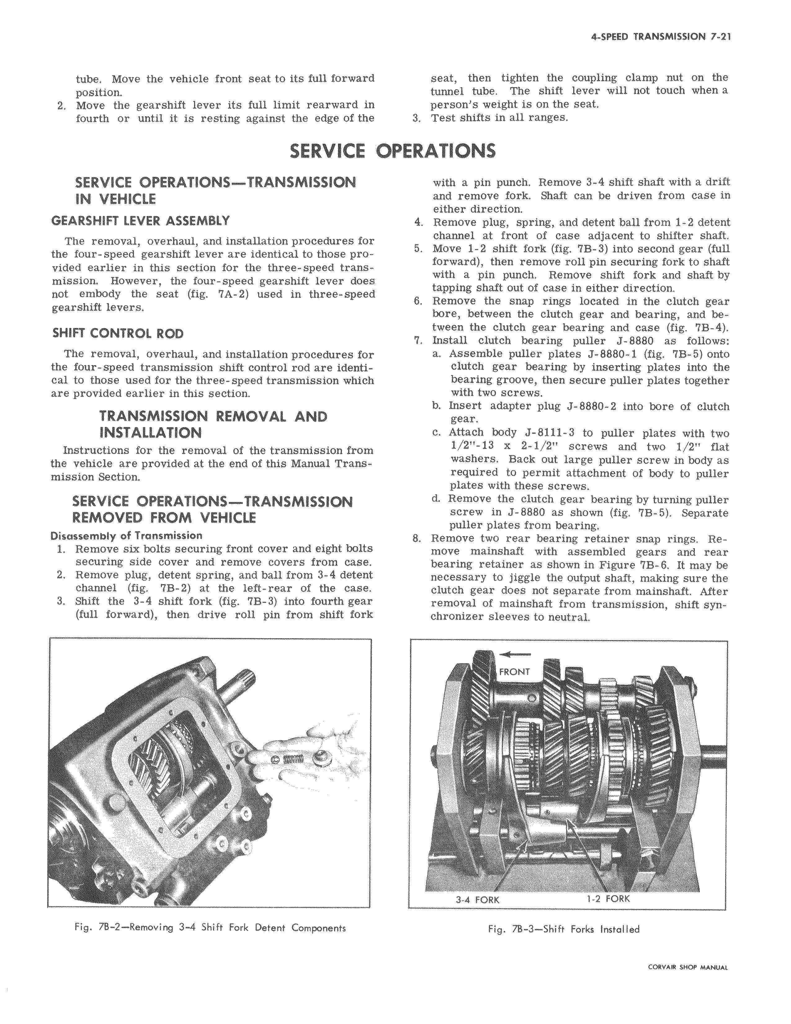
tube Move the vehicle front seat to its full forward position 2 Move the gearshift lever its full limit rearward in fourth or until it is resting against the edge of the SERVICE v SERVICE OPERATIONS TRANSMISSION IN VEHICLE GEARSHIFT LEVER ASSEMBLY The removal overhaul and installation procedures for the four speed gearshift lever are identical to those provided earlier in this section for the three speed transmission However the four speed gearshift lever does not embody the seat fig 7A 2 used in three speed gearshift levers SHIFT CONTROL ROD The removal overhaul and installation procedures for the four speed transmission shift control rod are identical to those used for the three speed transmission which are provided earlier in this section TRANSMISSION REMOVAL AND INSTALLATION Instructions for the removal of the transmission from the vehicle are provided at the end of this Manual Transmission Section SERVICE OPERATIONS TRANSMISSION REMOVED FROM VEHICLE Disassembly of Transmission I Remove six bolts securing front cover and eight bolts securing side cover and remove covers from case 2 Remove plug detent spring and ball from 3 4 detent channel fig 7B 2 at the left rear of the case 3 Shift the 3 4 shift fork fig 7B 3 into fourth gear full forward then drive roll pin from shift fork seat then tighten the coupling clamp nut on the tunnel tube The shift lever will not touch when a person s weight is on the seat 3 Test shifts in all ranges PERATIONS with a pin punch Remove 3 4 shift shaft with a drift and remove fork Shaft can be driven from case in either direction 4 Remove plug spring and detent ball from 1 2 detent channel at front of case adjacent to shifter shaft 5 Move 1 2 shift fork fig 7B 3 into second gear full forward then remove roll pin securing fork to shaft with a pin punch Remove shift fork and shaft by tapping shaft out of case in either direction 6 Remove the snap rings located in the clutch gear bore between the clutch gear and bearing and between the clutch gear bearing and case fig 7B 4 7 Install clutch bearing puller J 8880 as follows a Assemble puller plates J 8880 1 fig 7B 5 onto clutch gear bearing by inserting plates into the bearing groove them secure puller plates together with two screws b Insert adapter plug J 8880 2 into bore of clutch gear c Attach body J 8111 3 to puller plates with two 1 2 13 x 2 1 2 screws and two 1 2 flat washers Back out large puller screw in body as required to permit attachment of body to puller plates with these screws d Remove the clutch gear bearing by turning puller screw in J 8880 as shown fig 7B 5 Separate pulier plates from bearing 8 Remove two rear bearing retainer snap rings Remove mainshaft with assembled gears and rear bearing retainer as shown in Figure 7B 6 It may be necessary to jiggle the output shaft making sure the clutch gear does not separate from mainshaft After removal of mainshaft from transmission shift synchronizer sleeves to neutral