Jeep Parts Wiki | Ford Parts Wiki
Home | Search | Browse
|
Corvair Chassis Shop Manual December 1964 |
|
Prev
 Next
Next
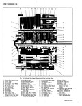
FOUR SPEED n Page General Description 7 lg Maintenance and Adjustments 7 lg Lubrication 7 19 Shift Linkage Adjustment 7 ig Service Operations 7 21 Service Operations Transmission in Vehicle 7 21 Gearshift Lever Assembly 7 21 Shift Control Rod 7 21 Service Operations Power Train Removed from Vehicle 7 21 Disassembly of Transmission 7 gl Disassembly of Mainshaft 7 22 GENERAL The Corvair four speed transmission fig 7B 1 is of the helical gear constant mesh type to provide full synchronization in all forward gears Spur gears on the mainshaft and countershaft are engaged by a small sliding spur gear to provide reverse Reverse is not synchronized Like the Corvair three speed the four speed mainshaft is hollow to permit passage of the clutch shaft forward to the clutch gear The mainshaft is supported at the front in a double row of needle bearings carried by the clutch gear and at the rear by a ball bearing race 7n turn the clutch gear is carried in the front of the case by a ball bearing race The countergear is of a single piece construction and is carried on double rows of needle bearings at each end Thrust washers are used both front and rear between the countergear and the transmission case A slight press fit is used at the front of the countershaft to retain the shaft and to prevent lubrication loss at this point Vehicle shift components are comparable to those used with the Corva ir three speed transmission A long shift tube supported by a nylon bushed bracket in the tunnel spans the distance between the driver s compartment and MAINTENANCE r LUBRICATION Common lubricant specified in Section 0 is used in the four speed transmission and differential carrier so no oil seals are used between these units Actually there is some interchange of lubricant as a lubricant dam is formed at the transmission which prevents entrapment of excess lube in the carrier sump which is below the transmission level thus maintaining transmission lubrication on upgrades Oil Level Check Periodically check the lubricant of the four speed Transaxle by removing the filler plug in the differential carrier If oil is at the level of carrier filler plug both the carrier and transmission lubricant levels are satisfactory If oil is below filler plug add oil to the carrier as required then check the lubricant level in the transmission by removing its filler plug Replenish as necessary TRANSMISSION NDEX Page Inspection and Repair 7 23 Transmission Case 7 23 Front and Rear Bearings 7 23 Bearing Rollers and Spacers 7 23 Gears and Thrust Washers 7 23 Clutch Keys and Springs 7 23 Rear Bearing Race Replacement 7 24 Assembly of Mainshaft 7 24 Assembly of Transmission 7 25 Transmission Removal and Installation 7 27 Special Tools 7 28 DESCRIPTION the front of the transmission At the front the tunnel shift tube carries a ball socket to receive the lower end of the gearshift lever A rubber sleeved coupling is secured by a clamp nut to the tunnel shift tube at the rear to provide attachment to the transmission shift rod and to provide a means of adjusting the length of the tunnel tube for linkage adjustment Thus by moving the gearshift lever shift tube motion is provided both fore and aft and laterally In the transmission three shift fork rods are mounted parallel above the transmission shift rod which is attached to the tunnel shift tube The transmission shift rod carries a finger which extends upward to engage the shift forks As the three forks are mounted on parallel rods a slight rotation of the shift rod moves the shift finger from the 1 2 fork in the center to the 3 4 fork which is outboard To engage the reverse shifter head which is mounted on the inboard shaft the shift finger must be moved laterally against a spring loaded plunger at the neutral crossover point The plunger is required to prevent accidental shifting into reverse while in motion as the 1 2 fork has a gate to permit passage of the shift finger through it to reach reverse AND ADJUSTMENTS CAUTION Under no circumstances should any lubricant containing active sulphur be used Also do not use mineral oil Only lubricant specified in Section 0 should be used Oil Change To change oil drain both the differential carrier and four speed transmission by removing the drain plug provided in each Reinstall the drain plugs and refill each unit to the level of the filler plugs with Lubricant specified in Section 0 SHIFT LINKAGE ADJUSTMENT After any service operation in which the shift control rod in the tunnel has been replaced or it has been found that transmission response is improper to the shift pattern adjust the shift linkage 1 Shift the transmission to fourth then loosen the coupling clamp nut fig 7A 3 on the tunnel shift