Jeep Parts Wiki | Ford Parts Wiki
Home | Search | Browse | Marketplace | Messages | FAQ | Guest
|
Corvair Chassis Shop Manual December 1964 |
|
Prev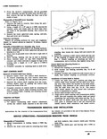
 Next
Next
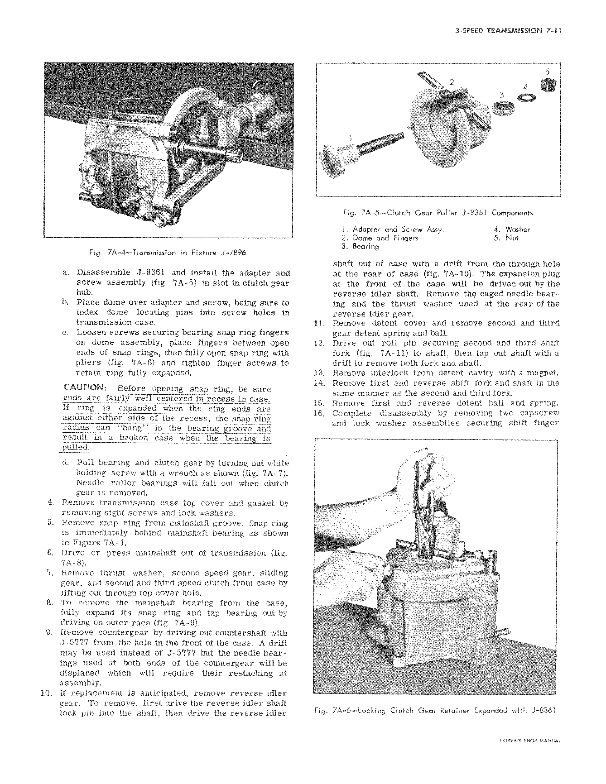
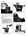
7 4 l 7 Fig 7A 4 Transmission in Fixture J 7896 a Disassemble J 8381 and install the adapter and screw assembly fig 7A 5 in slot in clutch gear hub b Place dome over adapter and screw being sure to index dome locating pins into screw holes in transmission case c Loosen screws securing bearing snap ring fingers on dome assembly place fingers between open ends of snap rings then fully open snap ring with pliers fig 7A 6 and tighten finger screws to retain ring fully expanded CAUTION Before opening snap ring be sure ends are fair y we centered in recess in case If ring is expanded when the ring ends are against either side of the recess the snap ring radius can hang in the bearing groove and result in a broken case when the bearing is pulled d Pull bearing and clutch gear by turning nut while holding screw with a wrench as shown fig 7A 7 Needle roller bearings will fall out when clutch gear is removed 4 Remove transmission case top cover and gasket by removing eight screws and lock washers 5 Remove snap ring from mainshaft groove Snap ring is immediately behind mainshaft bearing as shown in Figure 7A 1 6 Drive or press mainshaft out of transmission fig 7A 8 7 Remove thrust washer second speed gear sliding gear and second and third speed clutch from case by lifting out through top cover hole 8 To remove the mainshaft bearing from the case fully expand its snap ring and tap bearing out by driving on outer race fig 7A 9 9 Remove countergear by driving out countershaft with J 5777 from the hole in the front of the case A drift may be used instead of J 5777 but the needle bearings used at both ends of the countergear will be displaced which will require their restacking at assembly 10 If replacement is anticipated remove reverse idler gear To remove first drive the reverse idler shaft lock pin into the shaft then drive the reverse idler 5 r 2 xt 1 t Y 3 4 Fig 7A 5 Clutch Gear Puller J 8361 Components 1 Adapter and Screw Assy 4 Washer 2 Dome and Fingers 5 Nut 3 Bearing shaft out of case with a drift from the through hole at the rear of case fig 7A 10 The expansion plug at the front of the case will be driven out by the reverse idler shaft Remove the caged needle bearing and the thrust washer used at the rear of the reverse idler gear 11 Remove detent cover and remove second and third gear detent spring and ball 12 Drive out roll pin securing second and third shift fork fig 7A 11 to shaft then tap out shaft with a drift to remove both fork and shaft 13 Remove interlock from detent cavity with a magnet 14 Remove first and reverse shift fork and shaft in the same manner as the second and third fork 15 Remove first and reverse detent ball and spring 16 Complete disassembly by removing two capscrew and lock washer assemblies securing shift finger a a hY Fig 7A 6 Locking Clutch Gear Retainer Expanded with J 8361