Jeep Parts Wiki | Ford Parts Wiki
Home | Search | Browse | Marketplace | Messages | FAQ | Guest
|
Corvair Chassis Shop Manual December 1964 |
|
Prev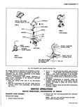

 Next
Next
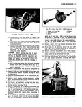
3 From the driver s compartment lift the gearshift lever assembly up until its studs clear the floor pan then remove the unit by lifting the floor mat at the center of seat Disassembly of Gearshift Lever Assembly Refer to Figure 7A 2 1 Unscrew the knob to remove then clamp the gear shift housing in a vise 2 Using a length of 1 1 2 pipe or J 5590 depress the retainer plate and rotate until its three lugs clear the lands in the gearshift housing then remove the retainer 3 Remove the lower spherical joint spring and seat then pull lever out of housing Inspection and Repair Inspect all working surfaces for wear and roughness Repair or replace pieces as required If broken replace the spring I Assembly of Gearshift Lever Assembly Fig 7A 2 1 Apply Lubriplate generously to all working surfaces 2 Place retainer plate on lower spherical and place the housing in a vise 3 Place seat on gearshift lever with tab to right side of housing 4 Place spring bushing and cup on seat in housing 5 Place retainer plate on cup then compress the retainer and rotate laterally to engage its lugs in the I housing with a length of 1 1 2 pipe or J 5590 if available 6 Complete assembly by installing knob on shift lever SHIFT CONTROL SHAFT I Removat of Control Shaft from Vehicle 1 Remove tunnel cover and control shaft insulators 2 To remove connecting pin first remove cotter then remove pin by pushing out with channel lock pliers 3 Separate the control shaft coupling from the transmission shifter shaft by pushing the control shaft toward the front of the car 4 Complete removal of control shaft by removing two nuts attaching control shaft mounting bracket then remove control shaft coupling and mounting bracket as an assembly Inspection and Repair Coupling Replacement 1 To insure maintaining shift control adjustment scribe the control shaft adjacent to the end of the TRANSMISSION REMOVA Instructions for the removal of the transmission from SERVICE OPERATIONS TRANSMIS IM Disassembly of Transmission 1 Mount transmission in holding fixture J 7896 fig 7A 4 2 Remove the front cover plate by removing four boltsi I V F 1 Fig 7A 3 Control Rod Linkage coupling then loosen the clamp bolt and remove old coupling 2 Insert new coupling in shift control shaft until the end of the coupling is aligned with the mark scribed in Step 1 Rotate coupling so attaching pin hole at transmission end is vertical then tighten clamp bolt ControlSNaft Front Mounting Bracket or Bushing Replacement 1 Remove the coupling as previously described 2 Slide bracket and bushing assembly fig 7A 2 off control shaft 3 Reinstall bracket with reinforced side toward rear of shaft then install coupling as previously covered Installation of Control Shaft in Vehicle 1 Center the shift lever ball position and align the control shaft front bracket with the shift lever housing year then insert the bracket on its studs simultanequsly with insertion of the control shaft socket onto the shift lever ball fig 7A 2 The control shaft socket should be well coated with Lubriplate prior to installation in vehicle 2 Secure shaft bracket with two nuts 3 Align control shaft coupling with transmission shifter shaft then pull coupling over shifter shaft and install connecting pin and secure with cotter pin fig 7A 3 4 Snapi boot of shifter shaft seal into place in tunnel rear plate if loosened and it was not removed and installl control shaft insulators and tunnel covers vL AND I INSTALLATION the vehicle are provided at the end of this Manual Transmission Section i I REMOVED FROM VEHICLE and lock washers then remove clutch gear bearing snapi ring 3 Remove the clutch gear and bearing with J 8381 as follows