Jeep Parts Wiki | Ford Parts Wiki
Home | Search | Browse | Marketplace | Messages | FAQ | Guest
|
Corvair Chassis Shop Manual December 1964 |
|
Prev
 Next
Next
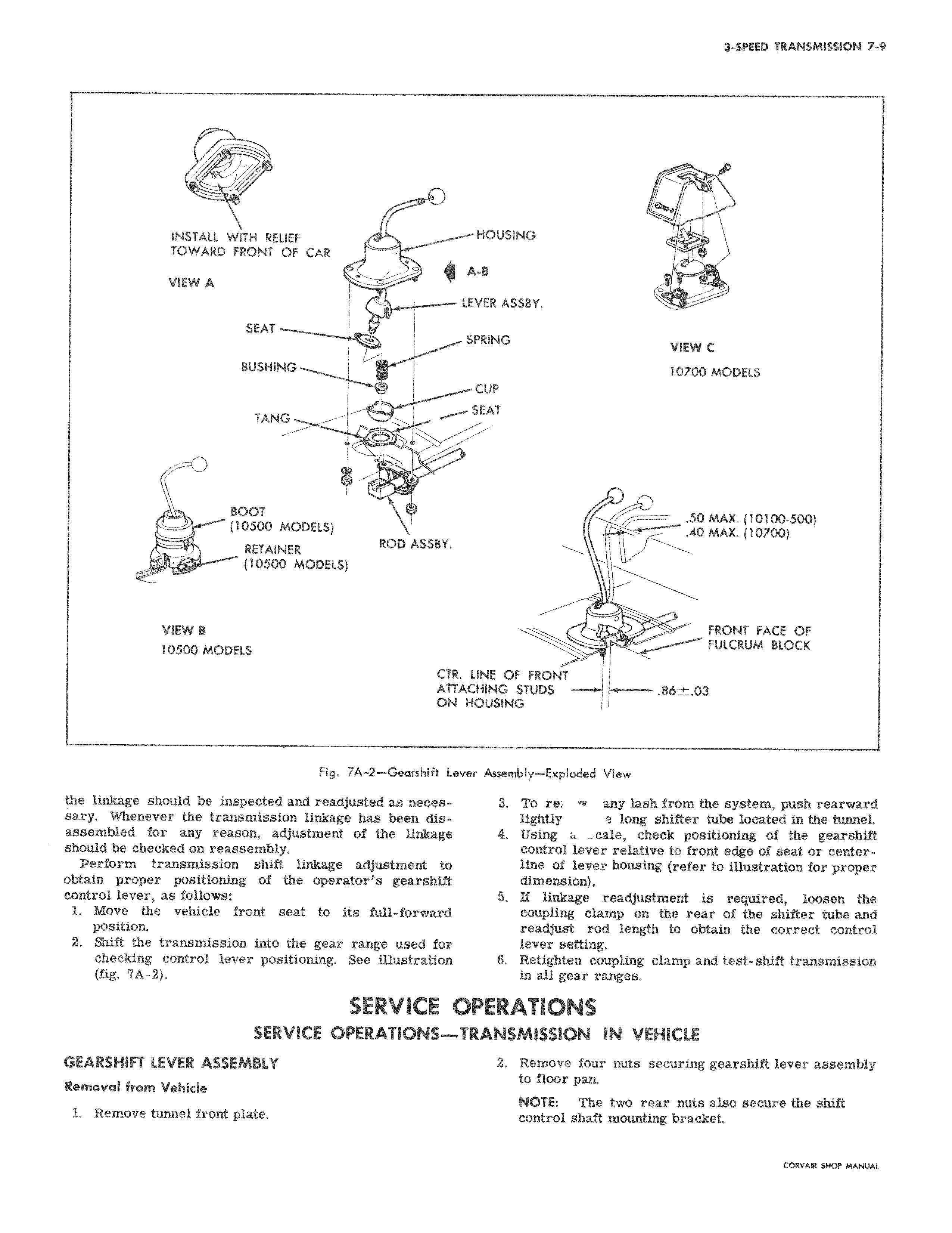
INSTALL WITH RELIEF TOWARD FRONT OF CAR VIEW A SEAT BUSHING TANG BOOT 10500 MODELS RETAINER ROD ASSBY 10500 MODELS VIEW B 10500 MODELS CT AT O Fig 7A 2 Gearshift L the linkage should be inspected and readjusted as necessary Whenever the transmission linkage has been disassembled for any reason adjustment of the linkage should be checked on reassembly Perform transmission shift linkage adjustment to obtain proper positioning of the operator s gearshift control lever as follows 1 Move the vehicle front seat to its full forward position 2 Shift the transmission into the gear range used for checking control lever positioning See illustration fig 7A 2 SERVICE SERVICE OPERATIONSGEARSHIFT LEVER ASSEMBLY Removal from Vehicle 1 Remove tunnel from plate w HOUSING A 8 0 LEVER ASSBY SPRING VIEW C 10700 MODELS CUP SEAT 50 MAX 10100 500 40 MAX 10700 FRONT FACE OF FULCRUM BLOCK t LINE OF FRONT rACHING STUDS 86 t 03 I HOUSING ever Assembly Exploded View 3 To rej any lash from the system push rearward lightly s long shifter tube located in the tunnel 4 Using 4 cale check positioning of the gearshift control lever relative to front edge of seat or centerline of lever housing refer to illustration for proper dimension 5 If linkage readjustment is required loosen the coupling clamp on the rear of the shifter tube and readjust rod length to obtain the correct control lever setting 8 Retighten coupling clamp and test shift transmission in all gear ranges OPERATIONS TRANSMISSION IN VEHICLE 2 Remove four nuts securing gearshift lever assembly to floor pan NOTE The two rear nuts also secure the shift control shaft mounting bracket