Jeep Parts Wiki | Ford Parts Wiki
Home | Search | Browse | Marketplace | Messages | FAQ | Guest
|
Corvair Chassis Shop Manual December 1964 |
|
Prev
 Next
Next
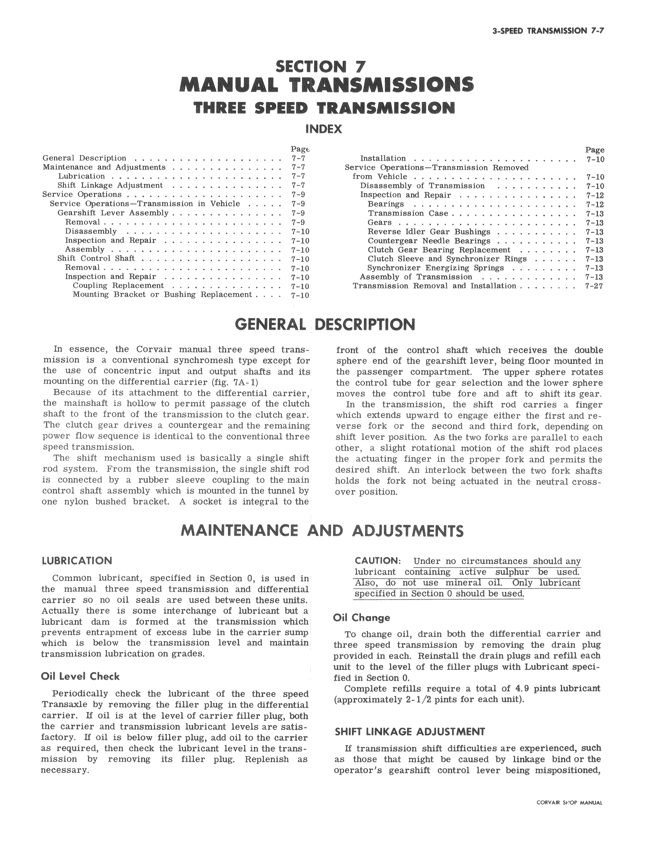
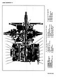
SECT MANUAL TO THREE SPEED it Pagc General Description 7 7 Maintenance and Adjustments 7 Lubrication 7 Shift Linkage Adjustment 7 7 Service Operations 7 9 Service Operations Transmission in Vehicle 7 9 Gearshift Lever Assembly 7 9 Removal 9 Disassembly 7 10 Inspection and Repair 7 10 Assembly 7 10 Shift Control Shaft 7 10 Removal 7 10 Inspection and Repair 7 10 Coupling Replacement 7 10 Mounting Bracket or Bushing Replacement 7 10 GENERAL In essence the Corvair manual three speed tramsmission is a conventional synchromesh type except for the use of concentric input and output shafts and its mounting on the differential carrier fig 7A 1 Because of its attachment to the differential carrier the mainshaft is hollow to permit passage of the clutch shaft to the front of the transmission to the clutch gear The clutch gear drives a countergear and the remaining power flow sequence is identical to the conventional three speed transmission The shift mechanism used is basically a single shift rod system From the transmission the single shift rod is connected by a rubber sleeve coupling to the main control shaft assembly which is mounted in the tunnel by one nylon bushed bracket A socket is integral to the MAINTENANCE ll LUBRICATION Common lubricant specified in Section 0 is used in the manual three speed transmission and differential carrier so no oil seals are used between these units Actually there is some interchange of lubricant but a lubricant dam is formed at the transmission which prevents entrapment of excess lube in the carrier sump which is below the transmission level and maintain transmission lubrication on grades Oil Level Check Periodically check the lubricant of the three speed Transaxle by removing the filler plug in the differential carrier If oil is at the level of carrier filler plug both the carrier and transmission lubricant levels are satisfactory If oil is below filler plug add oil to the carrier as required then check the lubricant level inthetransmission by removing its filler plug Replenish as necessary ION 7 ANSMISSIOHS TRANSMISSION IDEX Page Installation 7 10 Service Operations Transmission Removed from Vehicle 7 10 Disassembly of Transmission 7 10 Inspection and Repair 7 12 Bearings 7 12 Transmission Case 7 13 Gears 7 13 Reverse Idler Gear Bushings 7 13 Countergear Needle Bearings 7 13 Clutch Gear Bearing Replacement 7 13 Clutch Sleeve and Synchronizer Rings 7 13 Synchronizer Energizing Springs 7 13 Assembly of Transmission 7 13 Transmission Removal and Installation 7 27 DESCRIPTION front of the control shaft which receives the double sphere end of the gearshift lever being floor mounted in the passenger compartment The upper sphere rotates the control tube for gear selection and the lower sphere moves the control tube fore and aft to shift its gear In the transmission the shift rod carries a finger which extends upward to engage either the first and reverse fork or the second and third fork depending on shift lever position As the two forks are parallel to each other a slight rotational motion of the shift rod places the actuating finger in the proper fork and permits the desired shift An interlock between the two fork shafts holds the fork not being actuated in the neutral crossover position vND ADJUSTMENTS CAUTION Under no circumstances should any lubricant containing active sulphur used Also do not use mineral oil Only lubricirFt specified in Section 0 should be used Oil Change To change oil drain both the differential carrier and three speed transmission by removing the drain plug provided in each Reinstall the drain plugs and refill each unit to the level of the filler plugs with Lubricant specified in Section 0 Complete refills require a total of 4 9 pints lubricant approximately 2 1 2 pints for each unit SHIFT LINKAGE ADJUSTMENT If transmission shift difficulties are experienced such as those that might be caused by linkage bind or the operator s gearshift control lever being mispositioned