Jeep Parts Wiki | Ford Parts Wiki
Home | Search | Browse
|
Corvair Chassis Shop Manual December 1964 |
|
Prev

 Next
Next
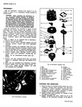
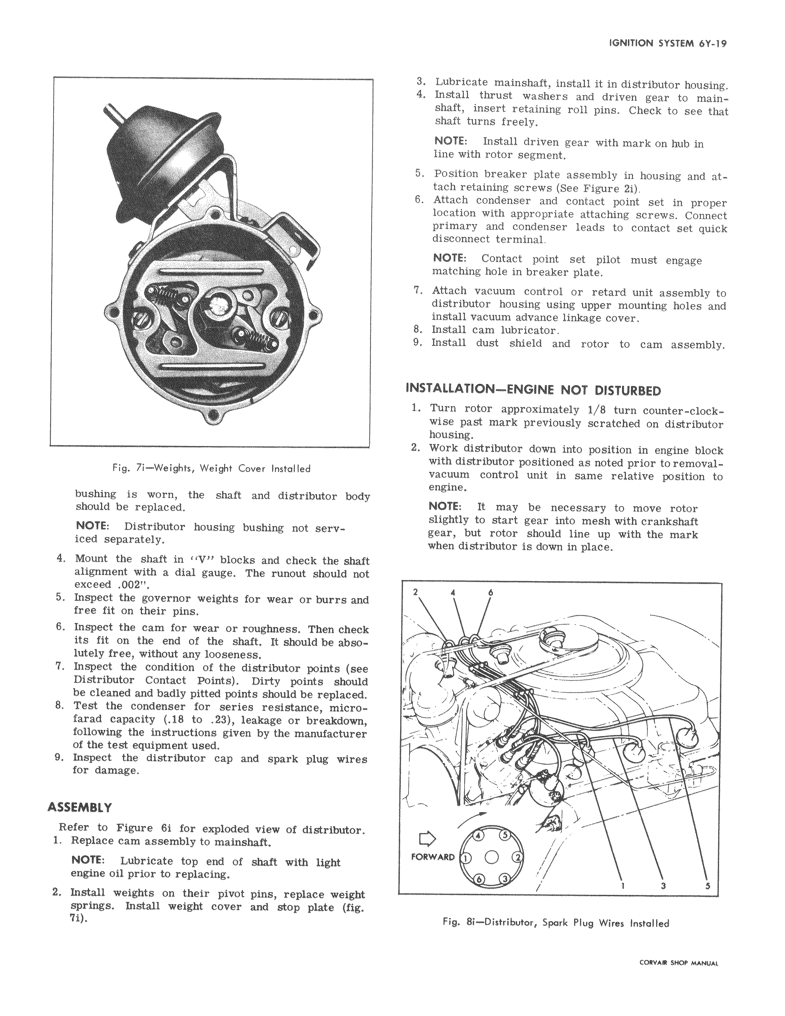
1 J v r r t Fig 7i Weights Weight Cover Installed bushing is worn the shaft and distributor body should be replaced NOTE Distributor housing bushing not serviced separately 4 Mount the shaft in IV blocks and check the shaft alignment with a dial gauge The runout should not exceed 002 5 Inspect the governor weights for wear or burrs and free fit on their pins 6 Inspect the cam for wear or roughness Then check its fit on the end of the shaft It should be absolutely free without any looseness 7 Inspect the condition of the distributor points see Distributor Contact Points Dirty points should be cleaned and badly pitted points should be replaced 8 Test the condenser for series resistance microfarad capacity 18 to 23 leakage or breakdown following the instructions given by the manufacturer of the test equipment used 9 Inspect the distributor cap and spark plug wires for damage ASSEMBLY Refer to Figure 61 for exploded view of distributor 1 Replace cam assembly to mainshaft NOTE Lubricate top end of shaft with light engine oil prior to replacing 2 Install weights on their pivot pins replace weight springs Install weight cover and stop plate fig 7i 3 Lubricate mainshaft install it in distributor housing 4 Install thrust washers and driven gear to mainshaft insert retaining roll pins Check to see that shaft turns freely NOTE Install driven gear with mark on hub in line with rotor segment 5 Position breaker plate assembly in housing and attach retaining screws See Figure 2i 6 Attach condenser and contact point set in proper location with appropriate attaching screws Connect primary and condenser leads to contact set quick disconnect terminal NOTE Contact point set pilot must engage matching hole in breaker plate 7 Attach vacuum control or retard unit assembly to distributor housing using upper mounting holes and install vacuum advance linkage cover 8 Install cam lubricator 9 Install dust shield and rotor to cam assembly INSTALLATION ENGINE NOT DISTURBED 1 Turn rotor approximately 1 8 turn counter clockwise past mark previously scratched on distributor housing 2 Work distributor down into position in engine block with distributor positioned as noted prior to removalvacuum control unit in same relative position to engine NOTE It may be necessary to move rotor slightly to start gear into mesh with crankshaft gear but rotor should line up with the mark when distributor is down in place 4 6 y I v f i r 4 S FORWARD 1 Q 6 3 1 3 S Fig 8i Distributor Spark Plug Wires Installed

 Next
Next