Jeep Parts Wiki | Ford Parts Wiki
Home | Search | Browse
|
Corvair Chassis Shop Manual December 1964 |
|
Prev

 Next
Next
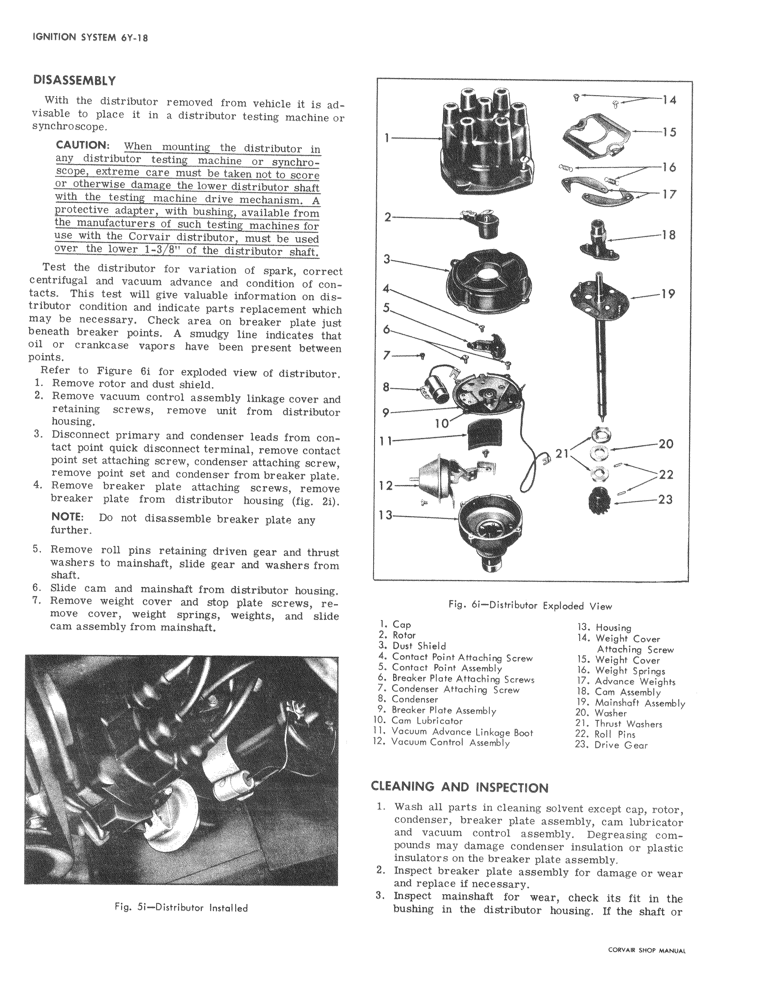
DISASSEMBLY With the distributor removed from vehicle it is adi visable to place it in a distributor testing machine or synchroscope CAUTION When mounting the distributor in i any distributor testing machine or synchroscope extreme care must be taken not to score or otherwise damage the lower distributor shaft with the testing machine drive mechanism A protective adapter with bushing available from the manufacturers of such testing machines for use with the Corvair distributor must be used over the lower 1 378 of the distributor shaft Test the distributor for variation of spark correct centrifugal and vacuum advance and condition of contacts This test will give valuable information on distributor condition and indicate parts replacement which may be necessary Check area on breaker plate just beneath breaker points A smudgy line indicates that l oil or crankcase vapors have been present between points Refer to Figure 6i for exploded view of distributor ll 1 Remove rotor and dust shield 2 Remove vacuum control assembly linkage cover and retaining screws remove unit from distributor housing 3 Disconnect primary and condenser leads from contact point quick disconnect terminal remove contact point set attaching screw condenser attaching screw remove point set and condenser from breaker plate 4 Remove breaker plate attaching screws remove breaker plate from distributor housing fig 2i NOTE Do not disassemble breaker plate any further 5 Remove roll pins retaining driven gear and thrust washers to mainshaft slide gear and washers from shaft 6 Slide cam and mainshaft from distributor housing I 7 Remove weight cover and stop plate screws re move cover weight springs weights and slide j cam assembly from mainshaft w Fig Si Distributor Installed 14 15 16 17 2 18 4 19 6 7 1 8 9 10 r 21 12 23 1 wlr3 Fig 6i Distributor Exploded View 1 Cap 13 Housing 2 Rotor 14 Weight Cover 3 Dust Shield Attaching Screw 4 Contact Point Attaching Screw 15 Weight Cover 5 Contact Point Assembly 16 Weight Springs 6 Breaker Plate Attaching Screws 17 Advance Weights 7 Condenser Attaching Screw 18 Cam Assembly 8 Condenser 19 Mainshaft Assembly 9 Breaker Plate Assembly 20 Washer 10 Cam Lubricator 21 Thrust Washers 11 Vacuum Advance Linkage Boot 22 Roll Pins 12 Vacuum Control Assembly 23 Drive Gear CLEANING AND INSPECTION 1 Wash all parts in cleaning solvent except cap rotor condenser breaker plate assembly cam lubricator and vacuum control assembly Degreasing compounds may damage condenser insulation or plastic insu4tors on the breaker plate assembly 2 Inspect breaker plate assembly for damage or wear and replace if necessary 3 Inspeet mainshaft for wear check its fit in the bushing in the distributor housing If the shaft or

 Next
Next