Jeep Parts Wiki | Ford Parts Wiki
Home | Search | Browse
|
Corvair Chassis Shop Manual December 1964 |
|
Prev

 Next
Next
1948791
1948791
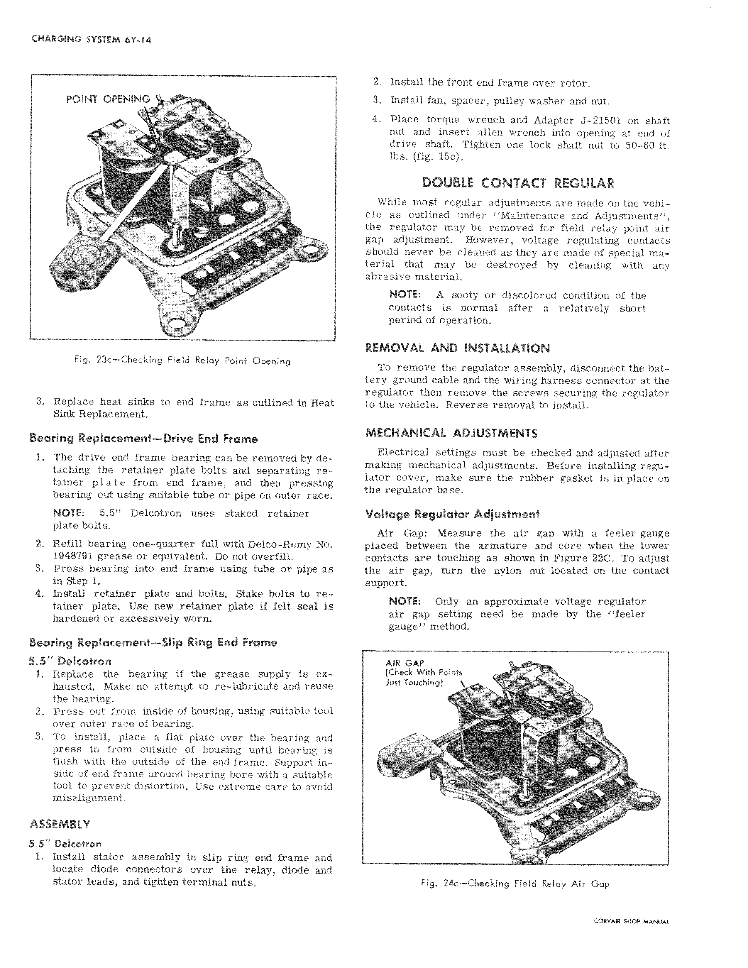
POINT OPENING Qo 7s i Fig 23c Checking Field Relay Point Opening II 3 Replace heat sinks to end frame as outlined in Heat Sink Replacement Bearing Replacement Drive End Frame 1 The drive end frame bearing can be removed by detaching the retainer plate bolts and separating retainer plate from end frame and then pressing bearing out using suitable tube or pipe on outer race NOTE 5 5 Delcotron uses staked retainer plate bolts 2 Refill bearing one quarter full with Delco Remy No 1948791 grease or equivalent Do not overfill 3 Press bearing into end frame using tube or pipe as in Step 1 4 Install retainer plate and bolts Stake bolts to retainer plate Use new retainer plate if felt seal i hardened or excessively worn Bearing Replacement Slip Ring End Frame 5 5 Delcotron 1 Replace the bearing if the grease supply is exhausted Make no attempt to re lubricate and reuse the bearing 2 Press out from inside of housing using suitable tool over outer race of bearing I 3 To install place a flat plate over the bearing and press in from outside of housing until bearing is flush with the outside of the end frame Support inside of end frame around bearing bore with a suitable tool to prevent distortion Use extreme care to avoid misalignment ASSEMBLY 5 5 Delcotron 1 Install stator assembly in slip ring end frame and locate diode connectors over the relay diode and stator leads and tighten terminal nuts 2 Install the front end frame over rotor 3 Install fan spacer pulley washer and nut 4 Place torque wrench and Adapter J 21501 on shaft nut and insert allen wrench into opening at end of drive shaft Tighten one lock shaft nut to 50 60 ft lbs fig 15c DOUBLE CONTACT REGULAR While i most regular adjustments are made on the vehicle as outlined under Maintenance and Adjustments the regulator may be removed for field relay point air gap adjustment However voltage regulating contacts should never be cleaned as they are made of special material that may be destroyed by cleaning with any abrasive material NOTE A sooty or discolored condition of the contacts is normal after a relatively short period of operation REMOVAL AND INSTALLATION To remove the regulator assembly disconnect the battery ground cable and the wiring harness connector at the regulator then remove the screws securing the regulator to the vehicle Reverse removal to install MECHANICAL ADJUSTMENTS Electrical settings must be checked and adjusted after making mechanical adjustments Before installing regulator cover make sure the rubber gasket is in place on the regulator base Voltage Regulator Adjustment Air Gap Measure the air gap with a feeler gauge placed between the armature and core when the lower contactsi are touching as shown in Figure 22C To adjust the air gap turn the nylon nut located on the contact support NOTE Only an approximate voltage regulator air gap setting need be made by the feeler gauge method AIR GAP Check With Points Just Touching a r v s Fig 24c Checking Field Relay Air Gap

 Next
Next