Jeep Parts Wiki | Ford Parts Wiki
Home | Search | Browse
|
Corvair Chassis Shop Manual December 1964 |
|
Prev
 Next
Next
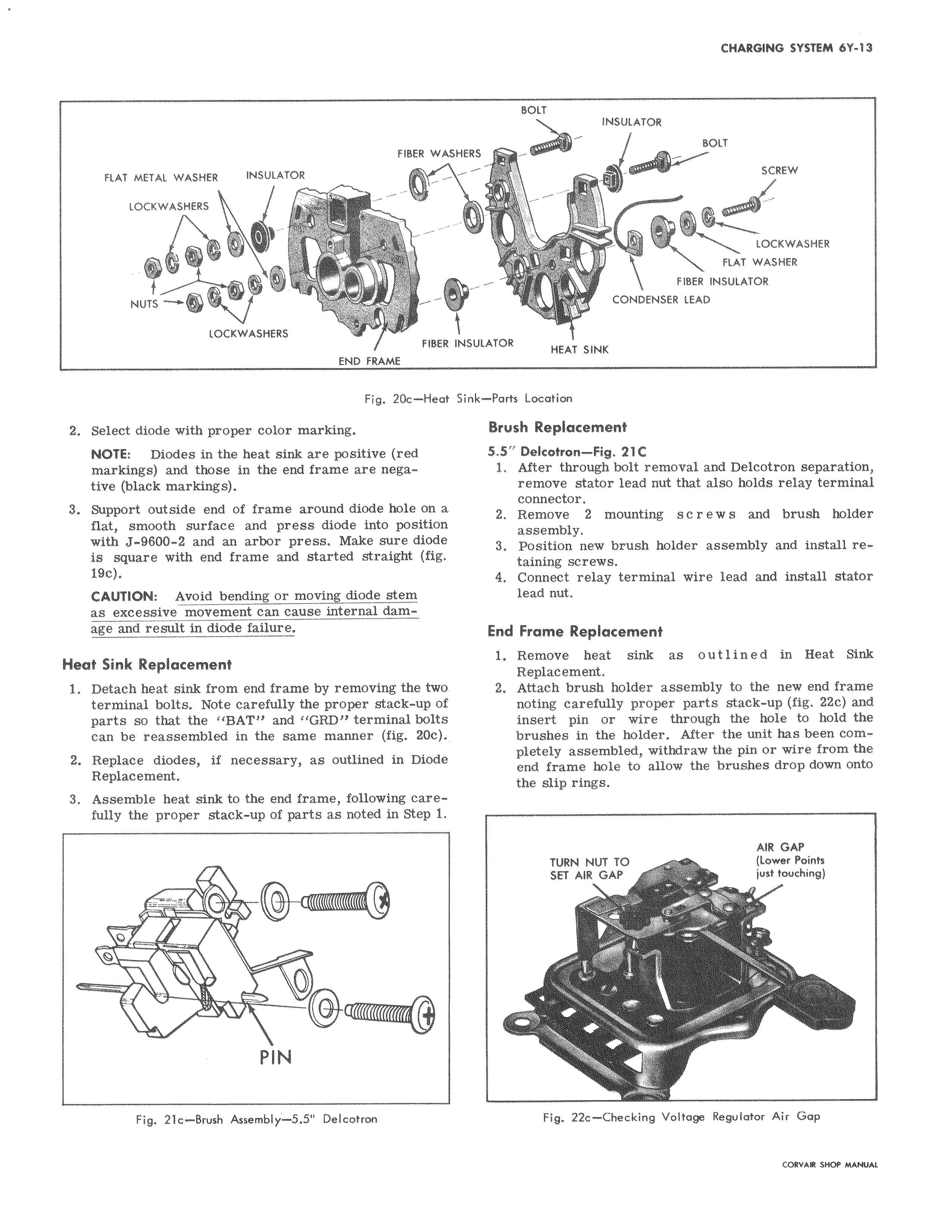
FIBER WAS FLAT METAL WASHER INSULATOR dL LOCKWASHERS NUTS wr LOCKWASHERS FIBER END FRAME Fig 20c Heat 2 Select diode with proper color marking NOTE Diodes in the heat sink are positive red markings and those in the end frame are negative black markings 3 Support outside end of frame around diode hole on a flat smooth surface and press diode into position with J 9600 2 and an arbor press Make sure diode is square with end frame and started straight fig 19c CAUTION Avoid bending or moving diode stem as excessive movement can cause internal damage and result in diode failure Heat Sink Replacement 1 Detach heat sink from end frame by removing the two terminal bolts Note carefully the proper stack up of parts so that the BAT and GRD terminal bolts can be reassembled in the same manner fig 20c 2 Replace diodes if necessary as outlined in Diode Replacement 3 Assemble heat sink to the end frame following carefully the proper stack up of parts as noted in Step 1 O 0 PIN Fig 21c Brush Assembly 5 5 Delcotron BOLT INSULATOR HERS BOLT SCREW LOCKWASHER FLAT WASHER FIBER INSULATOR CONDENSER LEAD NSULATOR HEAT SINK Sink Parts Location Brush Replacement 5 5 Delcotron Fig 21C 1 After through bolt removal and Delcotron separation remove stator lead nut that also holds relay terminal connector 2 Remove 2 mounting s c r e w s and brush holder assembly 3 Position new brush holder assembly and install retaining screws 4 Connect relay terminal wire lead and install stator lead nut End Frame Replacement 1 Remove heat sink as outlined in Heat Sink Replacement 2 Attach brush holder assembly to the new end frame noting carefully proper parts stack up fig 22c and insert pin or wire through the hole to hold the brushes in the holder After the unit has been completely assembled withdraw the pin or wire from the end frame hole to allow the brushes drop down onto the slip rings AIR GAP TURN NUT TO lower Points SET AIR GAP just touching Fig 22c Checking Voltage Regulator Air Gap