Jeep Parts Wiki | Ford Parts Wiki
Home | Search | Browse
|
Corvair Chassis Shop Manual December 1964 |
|
Prev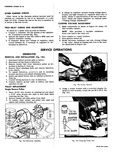
 Next
Next
NOTE Be sure wave washer is completely depressed DISASSEMBLY 1 Hold generator in a vise clamping the mounting flange lengthwise 2 Remove 4 thru bolts then break loose the end frames by prying at bolt locations 3 Remove the slip ring end frame and stator as an assembly from drive end and rotor assembly 4 Place a piece of tape over the slip ring end frame bearing to prevent entry of dirt or other foreign matter CAUTION Brushes may drop onto rotor shaft and become contaminated with bearing lubricant Clean brushes prior to installing with a nontoxic cleaner such as tri ehlorethylene 5 Remove the three stator lead attaching nuts and separate stator from end frame 6 Remove brush holder screws and brush holder assembly 7 Remove heat sink from end frame by removing batt and grd terminals and one attaching screw fig 20c 8 Remove slip ring end frame bearing if necessary by removing inner seal and slide 9 Remove drive pulley as outlined previously then remove rotor and spacers from end frame assembly 10 Remove drive end frame bearing retainer plate and bearing assembly from frame CLEANING AND INSPECTION With generator completely disassembled except for removal of diodes the components should be cleaned and inspected Be sure testing equipment is in good working order before attempting to check the generator 1 Wash all metal parts except stator and rotor assemblies CHECK FOR GROUNDS OHMMETER OHMMETER CHECK FOR SHORTS AND OPENS Fig 16c Checking Rotor for Grounds or Opens 2 Clean bearings and inspect for sealing pitting or roughness 3 Inspect rotor slip rings they may be cleaned with 400 grain polishing cloth Rotate rotor for this operation to prevent creating flat spots on slip rings 4 Slip rings which are out of round may be trued in a lathe to 001 maximum indicator reading Remove only enough material to make the rings smooth and concentric Finish with 400 grain polishing cloth and blow dry 5 Slip rings are not replaceable excessive damage will require rotor assembly replacement 6 Inspect brushes for wear If they are worn halfway replace Inspect brush springs for distortion or weakening If brushes appear satisfactory and move freely in brush holder springs may be reused TESTING ROTOR The rotor may be checked electrically with a 110 volt test lamp or an ohmmeter Grounds Connect test lamp or ohmmeter from either slip ring to the rotor shaft or to the rotor poles If the lamp lights or if the ohmmeter reading is low the field windings are grounded fig 16c Opens Connect one test lamp or ohmmeter lead to each slip ring If the lamp fails to light or if the ohmmeter reading is high the windings are open fig 16c Short Circuits The windings are checked for shorts by connecting a 12 volt battery and an ammeter in series with the two slip rings Note the ammeter reading An ammeter reading above the specified field amperage draw indicates shorted windings Refer to Specifications at the end of this section TESTING STATOR Grounds Connect a 110 volt test lamp or an ohmmeter from any stator lead to the stator frame If test lamp lights or if ohmmeter reads low the windings are grounded fig 17c Opens If lamp fails to light or if ohmmeter reads high when successively connected between each pair of stator leads the windings are open fig 1 c Short Circuits A short in the stator windings is difficult to locate without special test equipment due to the low resistance of the windings However if all other electrical checks are normal and the generator fails to supply rated output shorted windings are indicated Sometimes a shorted winding will show evidence of charring TESTING DIODES Two methods may be used to check diodes for shorts