Jeep Parts Wiki | Ford Parts Wiki
Home | Search | Browse
|
Corvair Chassis Shop Manual December 1964 |
|
Prev

 Next
Next
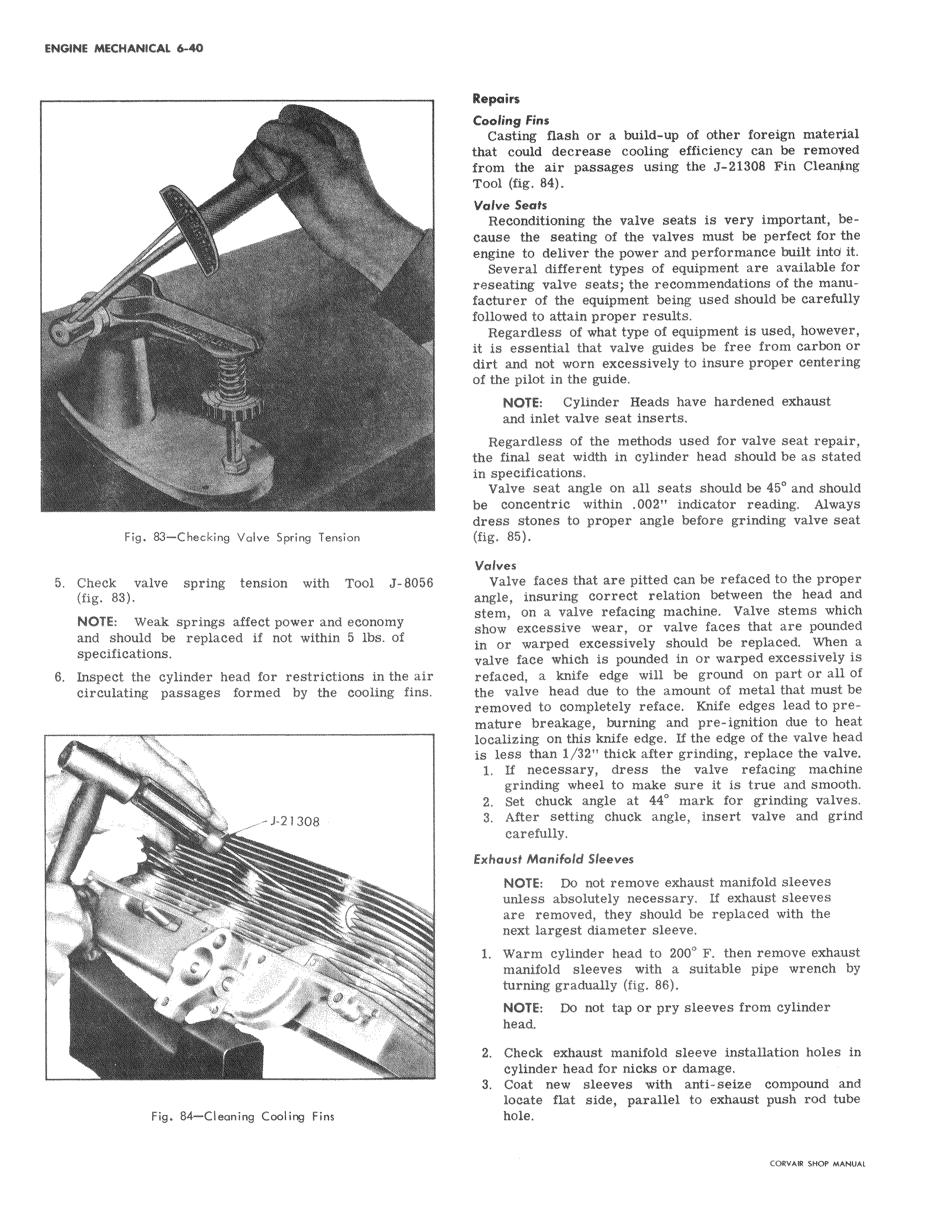
a v t f Repairf Cooling Fins Casting flash or a build up of other foreign material that could decrease cooling efficiency can be removed from the air passages using the J 21308 Fin Clean ng Tool fig 84 Valve eah Reconditioning the valve seats is very important because the seating of the valves must be perfect for the engine to deliver the power and performance built into it Several different types of equipment are available for reseating valve seats the recommendations of the manufacturer of the equipment being used should be carefully followed to attain proper results Regardless of what type of equipment is used however it is essential that valve guides be free from carbon or dirt artd not worn excessively to insure proper centering of the pilot in the guide NOTE Cylinder Heads have hardened exhaust and inlet valve seat inserts Reg trdless of the methods used for valve seat repair the final seat width in cylinder head should be as stated in spepifications Vahte seat angle on all seats should be 45 and should be concentric within 002 indicator reading Always dress stones to proper angle before grinding valve seat fig 85 Valves Valve faces that are pitted can be refaced to the proper angle insuring correct relation between the head and stem on a valve refacing machine Valve stems which show excessive wear or valve faces that are pounded in or warped excessively should be replaced When a valve face which is pounded in or warped excessively is refaced a knife edge will be ground on part or all of the valve head due to the amount of metal that must be removed to completely reface Knife edges lead to premature breakage burning and pre ignition due to heat localizing on this knife edge If the edge of the valve head is less than 1 32 thick after grinding replace the valve 1 IF necessary dress the valve refacing machine grinding wheel to make sure it is true and smooth 2 Set chuck angle at 44 mark for grinding valves 3 After setting chuck angle insert valve and grind carefully Exhaust Manifold Sleeves NOTE Do not remove exhaust manifold sleeves unless absolutely necessary If exhaust sleeves are removed they should be replaced with the next largest diameter sleeve 1 Warm cylinder head to 200 F then remove exhaust mlanifold sleeves with a suitable pipe wrench by tU rning gradually fig 86 NOTE Do not tap or pry sleeves from cylinder head 2 Check exhaust manifold sleeve installation holes in cylinder head for nicks or damage 3 Coat new sleeves with anti seize compound and locate flat side parallel to exhaust push rod tube hole

 Next
Next