Jeep Parts Wiki | Ford Parts Wiki
Home | Search | Browse
|
Corvair Chassis Shop Manual December 1964 |
|
Prev

 Next
Next
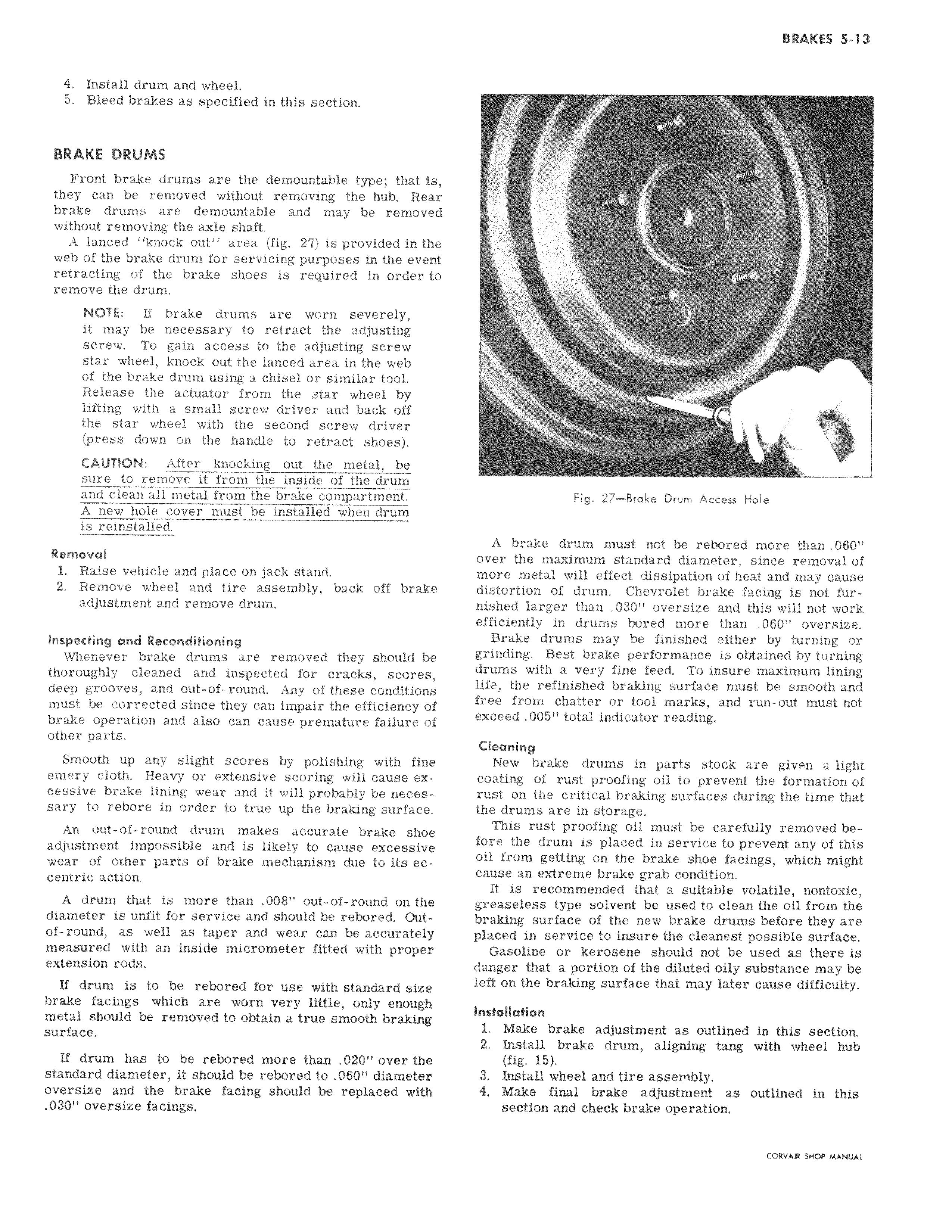
4 Install drum and wheel 5 Bleed brakes as specified in this section BRAKE DRUMS Front brake drums are the demountable type that is they can be removed without removing the hub Rear brake drums are demountable and may be removed without removing the axle shaft A lanced knock out area fig 27 is provided in the web of the brake drum for servicing purposes in the event retracting of the brake shoes is required in order to remove the drum NOTE If brake drums are worn severely it may be necessary to retract the adjusting screw To gain access to the adjusting screw star wheel knock out the lanced area in the web of the brake drum using a chisel or similar tool Release the actuator from the star wheel by lifting with a small screw driver and back off the star wheel with the second screw driver press down on the handle to retract shoes CAUTION After knocking out the metal be sure to remove it from the inside of the drum and clean all metal from the brake compartment A new hole cover must be installed when drum is reinstalled Removal 1 Raise vehicle and place on jack stand 2 Remove wheel and tire assembly back off brake adjustment and remove drum Inspecting and Reconditioning Whenever brake drums are removed they should be thoroughly cleaned and inspected for cracks scores deep grooves and out of round Any of these conditions must be corrected since they can impair the efficiency of brake operation and also can cause premature failure of other parts Smooth up any slight scores by polishing with fine emery cloth Heavy or extensive scoring will cause excessive brake lining wear and it will probably be necessary to rebore in order to true up the braking surface An out of round drum makes accurate brake shoe adjustment impossible and is likely to cause excessive wear of other parts of brake mechanism due to its eccentric action A drum that is more than 008 out of round on the diameter is unfit for service and should be rebored Outof round as well as taper and wear can be accurately measured with an inside micrometer fitted with proper extension rods If drum is to be rebored for use with standard size brake facings which are worn very little only enough metal should be removed to obtain a true smooth braking surface If drum has to be rebored more than 020 over the standard diameter it should be rebored to 060 diameter oversize and the brake facing should be replaced with 030 oversize facings Fig 27 Brake Drum Access Hole A brake drum must not be rebored more than 060 over the maximum standard diameter since removal of more metal will effect dissipation of heat and may cause distortion of drum Chevrolet brake facing is not furnished larger than 030 oversize and this will not work efficiently in drums bored more than 060 oversize Brake drums may be finished either by turning or grinding Best brake performance is obtained by turning drums with a very fine feed To insure maximum lining life the refinished braking surface must be smooth and free from chatter or tool marks and run out must not exceed 005 total indicator reading Cleaning New brake drums in parts stock are givPn a light coating of rust proofing oil to prevent the formation of rust on the critical braking surfaces during the time that the drums are in storage This rust proofing oil must be carefully removed before the drum is placed in service to prevent any of this oil from getting on the brake shoe facings which might cause an extreme brake grab condition It is recommended that a suitable volatile nontoxic greaseless type solvent be used to clean the oil from the braking surface of the new brake drums before they are placed in service to insure the cleanest possible surface Gasoline or kerosene should not be used as there is danger that a portion of the diluted oily substance may be left on the braking surface that may later cause difficulty Installation 1 Make brake adjustment as outlined in this section 2 Install brake drum aligning tang with wheel hub fig 15 3 Install wheel and tire assembly 4 Make final brake adjustment as outlined in this section and check brake operation CORVAYI SHOP MANUAL

 Next
Next