Jeep Parts Wiki | Ford Parts Wiki
Home | Search | Browse | Marketplace | Messages | FAQ | Guest
|
Corvair Chassis Shop Manual December 1964 |
|
Prev

 Next
Next
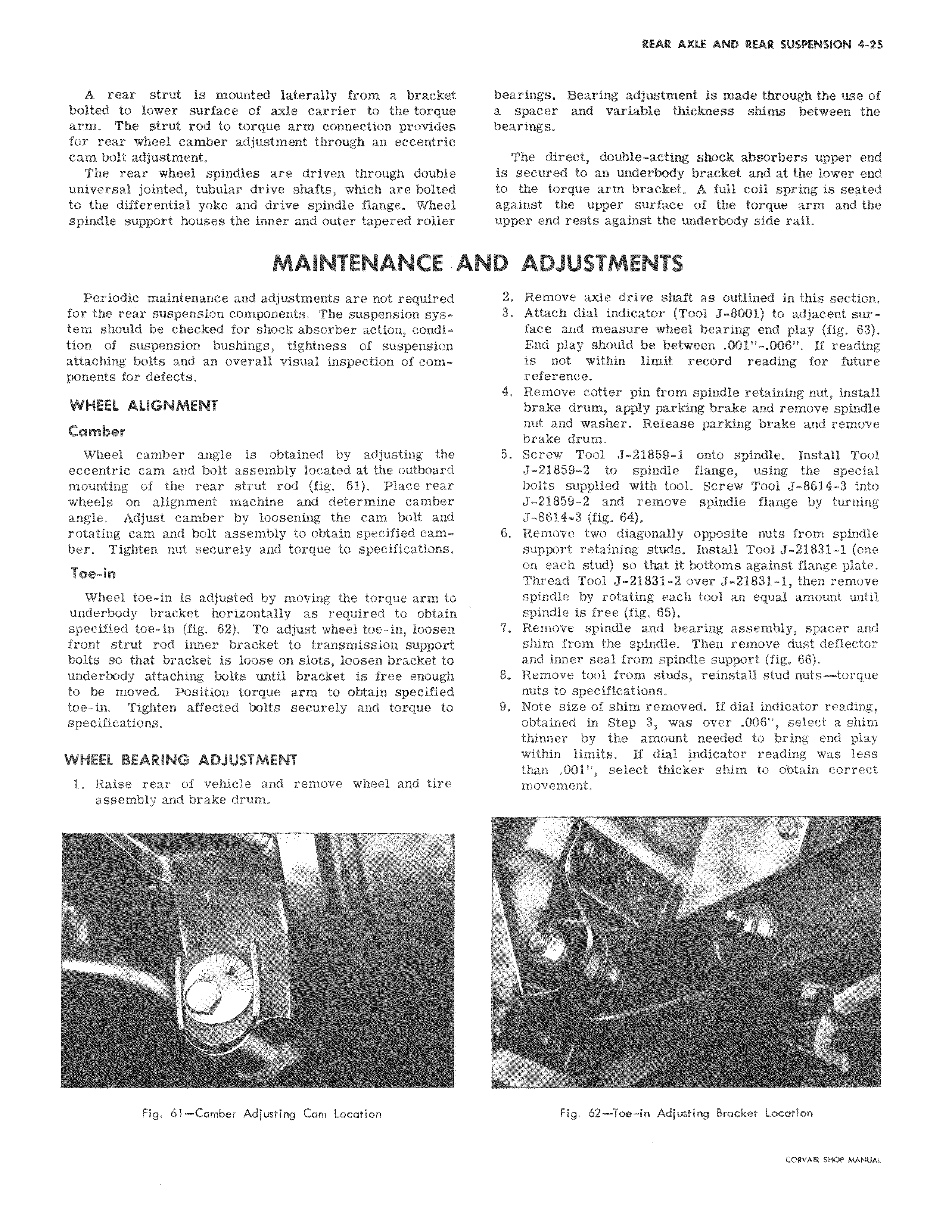
A rear strut is mounted laterally from a brackei bolted to lower surface of axle carrier to the torque arm The strut rod to torque arm connection providee for rear wheel camber adjustment through an eccentric cam bolt adjustment The rear wheel spindles are driven through doublE universal jointed tubular drive shafts which are boltec to the differential yoke and drive spindle flange Wheel spindle support houses the inner and outer tapered roliet MAINTENANCE Periodic maintenance and adjustments are not required for the rear suspension components The suspension system should be checked for shock absorber action condition of suspension bushings tightness of suspension attaching bolts and an overall visual inspection of components for defects WHEEL ALIGNMENT Camber Wheel camber angle is obtained by adjusting the eccentric cam and bolt assembly located at the outboard mounting of the rear strut rod fig 61 Place rear wheels on alignment machine and determine camber angle Adjust camber by loosening the cam bolt and rotating cam and bolt assembly to obtain specified camber Tighten nut securely and torque to specifications Toe in Wheel toe in is adjusted by moving the torque arm tc underbody bracket horizontally as required to obtair specified toe in fig 62 To adjust wheel toe in loosen front strut rod inner bracket to transmission support bolts so that bracket is loose on slots loosen bracket to underbody attaching bolts until bracket is free enough to be moved Position torque arm to obtain specified toe in Tighten affected bolts securely and torque to specifications WHEEL BEARING ADJUSTMENT 1 Raise rear of vehicle and remove wheel and tire assembly and brake drum Fig 61 Camber Adjusting Cam Location bearings Bearing adjustment is made through the use of a spacer and variable thickness shims between the bearings The direct double acting shock absorbers upper end is secured to an underbody bracket and at the lower end to the torque arm bracket A full coil spring is seated against the upper surface of the torque arm and the upper end rests against the underbody side rail AND ADJUSTMENTS 2 Remove axle drive shaft as outlined in this section 3 Attach dial indicator Tool J 8001 to adjacent surface and measure wheel bearing end play fig 63 End play should be between 001 006 If reading is not within limit record reading for future reference 4 Remove cotter pin from spindle retaining nut install brake drum apply parking brake and remove spindle nut and washer Release parking brake and remove brake drum 5 Screw Tool J 21859 1 onto spindle Install Tool J 21859 2 to spindle flange using the special bolts supplied with tool Screw Tool J 8614 3 nto J 21859 2 and remove spindle flange by turning J 8614 3 fig 64 6 Remove two diagonally opposite nuts from spindle support retaining studs Install Tool J 21831 1 one on each stud so that it bottoms against flange plate Thread Tool J 21831 2 over J 21831 1 then remove spindle by rotating each tool an equal amount until spindle is free fig 65 7 Remove spindle and bearing assembly spacer and shim from the spindle Then remove dust deflector and inner seal from spindle support fig 66 8 Remove tool from studs reinstall stud nuts torque nuts to specifications 9 Note size of shim removed If dial indicator reading obtained in Step 3 was over 006 select a shim thinner by the amount needed to bring end play within limits If dial indicator reading was less than 001 select thicker shim to obtain correct movement d Fig 62 Toe in Adjusting Bracket Location CORVAR SHOP MMKIAI

 Next
Next