Jeep Parts Wiki | Ford Parts Wiki
Home | Search | Browse
|
Corvair Chassis Shop Manual December 1964 |
|
Prev

 Next
Next
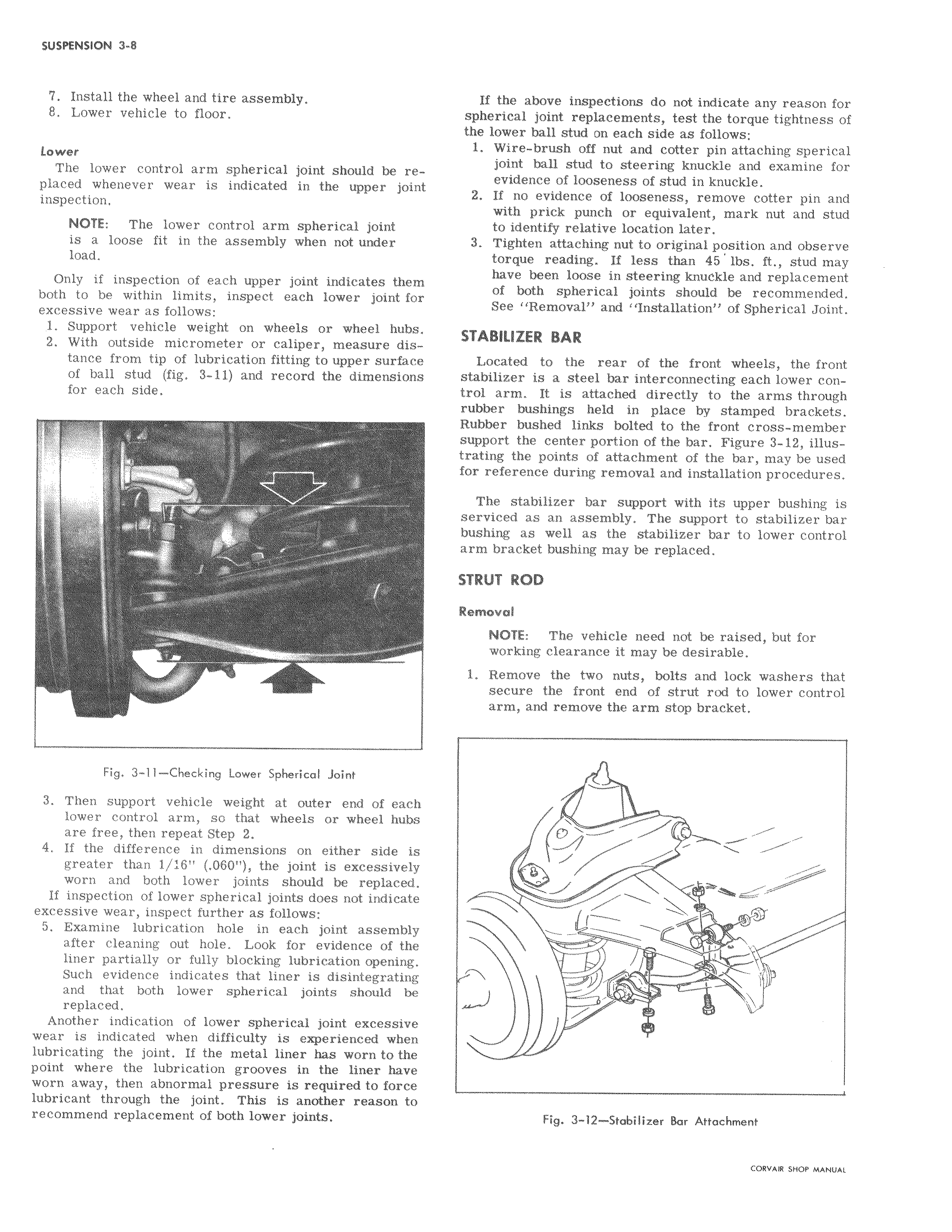
I 7 Install the wheel and tire assembly 8 Lower vehicle to floor I Lower The lower control arm spherical joint should be re 1I placed whenever wear is indicated in the upper join inspection NOTE The lower control arm spherical joint is a loose fit in the assembly when not under load Only if inspection of each upper joint indicates them both to be within limits inspect each lower joint for excessive wear as follows 1 Support vehicle weight on wheels or wheel hubs 2 With outside micrometer or caliper measure distance from tip of lubrication fitting to upper surface of ball stud fig 3 11 and record the dimensions for each side Fig 3 11 Checking Lower Spherical joint 3 Then support vehicle weight at outer end of each lower control arm so that wheels or wheel hubs are free then repeat Step 2 4 If the difference in dimensions on either side is greater than 1 16 060 the joint is excessively worn and both lower joints should be replaced If inspection of lower spherical joints does not indicat excessive wear inspect further as follows 5 Examine lubrication hole in each joint assembl after cleaning out hole Look for evidence of th liner partially or fully blocking lubrication opening Such evidence indicates that liner is disintegrati and that both lower spherical joints should b replaced Another indication of lower spherical joint excessiv wear is indicated when difficulty is experienced whe lubricating the joint If the metal liner has worn to th point where the lubrication grooves in the liner hav worn away then abnormal pressure is required to fore lubricant through the joint This is another reason t recommend replacement of both lower joints I If the above inspections do not indicate any reason for sphericai joint replacements test the torque tightness of the lowei ball stud on each side as follows 1 Wire brush off nut and cotter pin attaching sperical join ball stud to steering knuckle and examine for evidlence of looseness of stud in knuckle 2 If no evidence of looseness remove cotter pin and wit1N prick punch or equivalent mark nut and stud to identify relative location later 3 Tighten attaching nut to original position and observe torque reading If less than 45 lbs ft stud may have been loose in steering knuckle and replacement of both spherical joints should be recommended See Removal and Installation of Spherical Joint STABILIIER BAR Located to the rear of the front wheels the front stabilizer is a steel bar interconnecting each lower control arnti It is attached directly to the arms through rubber bushings held in place by stamped brackets Rubber bushed links bolted to the front cross member support the center portion of the bar Figure 3 12 illustrating the points of attachment of the bar may be used for reference during removal and installation procedures The stabilizer bar support with its upper bushing is serviced as an assembly The support to stabilizer bar bushing as well as the stabilizer bar to lower control arm bracket bushing may be replaced STRUT ROD Removal NOTE The vehicle need not be raised but for working clearance it may be desirable 1 Remove the two nuts bolts and lock washers that sectpre the front end of strut rod to lower control arm and remove the arm stop bracket w i Fig 3 12 Stabilizer Bar Attachment

 Next
Next